PSLab Android app by FOSSASIA can be used to visualize different waveforms, signal levels and patterns. Many of them involve logging data from different instruments. These data sets can be unique and the user might want them to be specific to a location or a time. To facilitate this feature, PSLab Android app offers a feature to save user’s current location along with the data points.
This implementation can be done in two ways. One is to use Google Maps APIs and the other one is to use LocationManager classes provided by Android itself. The first one is more on to proprietary libraries and it will give errors when used in an open source publishing platform like Fdroid as they require all the libraries used in an app to be open. So we have to go with the latter, using LocationManager classes.
As first step, we will have to request permission from the user to allow the app access his current location. This can be easily done by adding a permission tag in the Manifest.xml file.
Since we are not using Google Maps APIs, capturing the current location will take a little while and that can be considered as the only downfall of using this method. We have to constantly check for a location change to capture the data related to current location. This can be easily done by attaching a LocationListener as it will do the very thing for us.
In case if the user has turned off GPS in his device, this method wouldn’t work. We will have to request him to turn the feature on using a simple dialog box or a bottom sheet dialog.
We can also customize how frequent the locationlistener should check for a location using another class named LocationManager. This class can be instantiated as follows:
Then we can easily set the time interval using requestLocationUpdates method. Here I have requested location updates in every one second. That is a quite reasonable rate.
Once we have set all this up, we can capture the current location assuming that the user has turned on the GPS option from his device settings and the LocationManager class has a new location as we checked earlier.
Each location will contain details related to its position such as latitudes and longitudes. We can log these data using the CSVLogger class implementation in PSLab Android app and let user have this option while doing his experiments.
Fdroid is a place for open source enthusiasts and developers to host their Free and Open Source Software (FOSS) for free and get more people onboard into their community. In order to host an app in their repository, one has to go through a several steps of builds and tests. This is to ensure that the software provided by them are as quality and safe as they can ever be. They are not allowing proprietary libraries or tools to integrate into any app or they will be published outside the Fdroid main repository (fdroid-data) so that the users will know what they are downloading.
In a normal Linux computer where we are developing Android apps and have setup Android Studio will not be able to run the build command using:
$ fdroid build -v -l org.fossasia.pslab
The reason behind this is that we have not installed gradle and build tools required by the “fdroid build” because they are not useful in our day today activities for standalone activities. First thing we need to do is, install gradle separately. This will include adding gradle to $PATH as well.
Download the latest gradle version zip file or the version your project is using with the following command. In PSLab Android app, we are using 4.5.1 version and the snippet below include that version.
Then we can add gradle to our $PATH variable using the following command:
$ export PATH=$PATH:/opt/gradle/gradle-4.5.1/bin
Now we are all set with gradle settings. Next step is to verify that the fdroid server is properly configured and up to date. When you run the build command after setting up the gradle in PC, it will throw an error similar to “failed to find any output apks”. This causes if the installed fdroid server version is old.
Fdroid server is running on python 3 and it will require some additional libraries pre-installed to properly function.
Pocket Science Lab by FOSSASIA is a compact tool that can be used for circuit analytics and debugging. To make things more interesting, this device can be accessed via the user interface using an Android app or also a desktop app. Both these apps use the UART protocol (Universal Asynchronous Receiver-Transmitter) to transmit commands to the PSLab device from mobile phone or PC and receive commands vice versa. The peculiar thing about hardware is that the developer cannot simply log data just like developing and debugging a software program. He needs some kind of an external mechanism or a tool to visualize those data packets travelling through the wires.
Figure 1: UART Interface in PSLab
PSLab has a UART interface extracted out simply for this reason and also to connect external sensors that use the UART protocol. With this, a developer who is debugging any of the Android app or the desktop app can view the command and data packets transmitted between the device and the user end application.
This requires some additional components. UART interface has two communication related pins: Rx(Receiver) and Tx(Transmitter). We will need to monitor both these pin signals for input and output data packets. It should be kept in mind that PSLab is using 3.3V signals. This voltage level is important to mention here because if someone uses 5V signals on these pins, it will damage the main IC. There are FTDI modules available in market. FTDI stands for Future Technology Devices International which is a company name and their main product is this USB transceiver chip. These chips play a major role in electronic industry due to product reliability and multiple voltage support. PSLab uses 3.3V USB Tx Rx pins and modules other than FTDI wouldn’t support it.
The module shown in Fig.2 is a FTDI module which you can simply plug in to computer and have a serial monitor interface. There are cheaper versions in shopping websites like eBay or Alibaba and they will also work fine. Both Tx and Rx pins will require two of these modules and connectivity is as follows;
This might look strange because everywhere we see a UART module is connected Rx → Tx and Tx → Rx. Notice that our idea is to monitor data packets. Not communicate with PSLab device directly. We want to see if our mobile phone Android app is sending correct commands to PSLab device or not and if PSLab device is transmitting back the expected result or not. This method helped a lot when debugging resistance measurement application in PSLab Android app.
Monitoring these UART data packets can be done simply using a serial monitor. You can either download and install some already built serial monitors or you can simply write a python script as follows which does the trick.
The Pocket Science Lab Android app being on the verge of development have various new features adding up per day. One of the new things added up recently is the splitting of the control section in three different instruments and implementing the control read section into a multimeter. This blog will be discussing about how the multimeter is implemented.
The different instruments are power section, multimeter and wave generator. While in the previous implementation of control section it was divided into three parts namely control main, control read and control advanced as shown in figure (1). The control is the power source, read is the multimeter and advanced section is the wave generator.
Figure (1): Screenshot of control section
Figure (1) shows the previous implementation of a multimeter i.e the read section but as we know this is way different than the actual implementation of a multimeter and thus from here comes the task of implementing a new multimeter.
What is a Multimeter, how does it looks?
A multimeter basically is an instrument designed to measure electric current, voltage, and usually resistance, typically over several ranges of value.
Figure (2): Showing a real multimeter instrument and its different sections [2]
Figure(2) clearly shows how an actual multimeter looks. It basically has three important components i.e the display the buttons and the rotary knob or the dial and thus the task was to implement the same in PSLab android.
Implementation in PSLab
Figure (3) : Screenshot of new implementation of multimeter
The implementation of multimeter is thus inspired from its original look i.e it has got basic buttons, a rotary knob and a display. Figure (3) shows the implementation of multimeter in the android-app
Back-end of Multimeter
A separate multimeter activity was implemented for the multimeter. The main back-end part of getting the resistance, capacitance, frequency and count pulse were taken from the communication related classes such as the ScienceLab class and PacketHandler class. For example to get the voltage calculation we use the getRawableVoltage function
The above function shows the pure backend of PSLab and how data is taken from the hardware using the packet handler class, after which the data is processed in various other functions after we getting the final result. Similarly the function to get count pulse is
As we see that the data is being taken through a similar manner in the above function i.e using the packetHandler class(by sending and receiving bytes). Thus in all the other functions for capacitance, frequency similar communication model can be found.
Similarly all the functions are implemented in the ScienceLab class and thus all the functions are directly called from the ScienceLab class in the Multimeter activity. For more knowledge on these one can directly have a look at the PSLab android app codes available in Github.
Implementation of the Rotary Knob
The rotary knob is implemented using the BeppiMenozzi Knob library. More information regarding the same can be found in my previous blog on implementing the rotary knob.
In PSLab android app, we have included sensor instruments which use either inbuilt sensor of smartphone or external sensor to record sensor data. For example, Lux Meter uses the light sensor to record lux data but the problem is that these instruments doesn’t contain settings option to configure the sensor record-setting like which sensor to use, change the update period etc.
Therefore, we need to create a settings page for the Lux Meter instrument which allows the user to modify the properties of the sensor instrument. For that I will use AndroidPreferenceAPIsto build a settings interface that is similar to setting activity in any other android app.
The main building block of the settings activity is the Preference object. Each preference appears as a single setting item in an activity and it corresponds to key-value pair which stores the settings in default Shared Preferences file. Every time any setting is changed by the user the Android will store the updated value of the setting in the default shared preferences which we can read in any other activity across the app.
In the following steps I will describe instruction on how to create the setting interface in Android app:
For this step, I have created a preference screen which will be inflated when the settings fragment is being created.
I created a file named “lux_meter_settings.xml” and place it in the res/xml/ directory.
The root node for the XML file must be a <PreferenceScreen> element. We have to add eachPreference within this element. Each child I added within the <PreferenceScreen> element appears as a single item in the list of settings.
The preference which I have used are:
<EdittextPreference>This preference opens up a dialog box with edit text and stores whatever value is written by the user in the edit text. I have used this preference for inputting update period and high limit of data during recording.
<CheckboxPreference> shows an item with a checkbox for a setting that is either enabled or disabled. The saved value is a boolean (true if it’s checked). I have used this preference for enabling or disabling location data with the recorded data.
<ListPreference> opens a dialog with a list of radio buttons. The saved value can be any one of the supported value types. I have used this preference to allow the user to choose between multiple sensor types.
<?xml version="1.0" encoding="utf-8"?><PreferenceScreenxmlns:android="http://schemas.android.com/apk/res/android"><EditTextPreferenceandroid:key="setting_lux_update_period"android:title="@string/update_period"android:dialogTitle="@string/update_period"android:defaultValue="1000"android:dialogMessage="Please provide time interval(in ms) at which data will be updated"android:summary="Update period is 900ms"/><EditTextPreferenceandroid:key="setting_lux_high_limit"android:title="High Limit"android:dialogTitle="High Limit"android:defaultValue="2000"android:dialogMessage="Please provide maximum limit of LUX value to be recorded"android:summary="High Limit is 2000 Lux"/><CheckBoxPreferenceandroid:defaultValue="false"android:key="include_location_sensor_data"android:summary="Include the location data in the logged file"android:title="Include Location Data" /></PreferenceScreen>
The above XML file will produce a layout as shown in Figure 1 below:
Figure 1 shows a preview of settings layout in Android Studio
Step 3 Implementing the backend of setting interface
As android Documentation clearly states:
As your app’s settings UI is built using Preference objects instead of View objects, you need to use a specialized Activity or Fragment subclass to display the list settings:
If your app supports versions of Android older than 3.0 (API level 10 and lower), you must build the activity as an extension of the PreferenceActivity class.
On Android 3.0 and later, you should instead use a traditional Activity that hosts a PreferenceFragment that displays your app settings.
Therefore, I first created an Activity named “SettingsActivity” which will act as a host for a Fragment. This gist contains code for SettingsActivity which I defined in the PSLab android app which will show the Setting Fragment.
Now, for setting fragment I have created a new fragment and name it “LuxMeterSettingsFragment” and make that fragment class extends the PreferenceFragmentCompat class and for which I needed to add this import statement.
This method is called when the Android is creating the Preferences that is when we need to call the method ‘setPreferencesFromResource()’ and pass the resource file in which we have defined our preferences along with the root key which comes as a parameter. Here, the Android will create preferences referred by the key which we have provided and initialize it to the default value in the default SharedPreferences file.
Step 4 Providing setting option to navigate to setting activity
First I included a setting option in the menu file which is getting inflated in the Lux Meter Activity toolbar as shown in below code.
Then, heading over to Lux Meter Activity in the onOptionItemSelected() method I added below code in which I created intent to open Setting Activity when the setting option is selected.
@OverridepublicbooleanonOptionsItemSelected(MenuItem item){
case R.id.settings:
Intent settingIntent = new Intent(this, SettingsActivity.class);
settingIntent.putExtra("title", "Lux Meter Settings");
startActivity(settingIntent);
break;
}
After this step, we can see the settings option in Lux Meter Activity as shown in Figure 2
Figure 2 shows the setting option in the overflow menu
To see if its working opens the app -> open Lux Meter Instrument-> Open Overflow Menu -> click on Lux Meter Setting Option to open settings.
Here we can the Lux Meter Setting as shown by the Figure 3.
Figure 3 shows the screenshot of the Lux Meter Setting activity on the actual device
Step 5 Implementing listener for change in Preferences item
Now, to register this listener with the Preference Screen which we will do it in the onResume() method of the fragment and deregister the listener in the onPause() method to correspond with the lifecycle of the fragment.
@Override
public void onResume() {
   super.onResume();

getPreferenceScreen().getSharedPreferences().registerOnSharedPreferenceChangeListener(this);
}
@Override
public void onPause() {
   super.onPause();
        getPreferenceScreen().getSharedPreferences().unregisterOnSharedPreferenceChangeListener(this);
}
Thus we have successfully implemented settings for the Lux Meter Instrument.
PSLab android application as we all know has got various instrument such as oscilloscope, logic analyzer, wave generator, etc.. . Although many of these instrument require redesigning of it’s UI. One such instrument is the Multimeter. The Multimeter UI required the implementation of the rotary knob as it is also present in an actual Multimeter.Thus this blog is solely on how to implement a Rotary Knob in an Android App.
Figure 1: Showing a basic knob
What is Rotary Knob ?
A Rotary knob is a customizable selector that replicates the behaviour of a knob with discrete values.The knob is a powerful tool it has a lot of advantages over other radio-buttons, seek bars or other selectors.[1][2]
It has an immediate graphical indication of the current value, the number of choices and where the value is in the overall range.
Works fine also with few choices, as a multi-state toggle.
Swipe gestures allow to change values very quickly, using the entire screen for the gesture, but only a tiny zone of it for the graphics.
Implementation of Rotary Knob in your app[1]
In this blog the rotary knob is implemented using the BeppiMenozzi Knob library[1] as by doing this we don’t have to manually create the extra class for the knob and we don’t have to write the code from scratch.
This blog will give you step by step guide on how to implement this on your app.
In your project level build.gradle file add the following lines of code.
This blog will demonstrate how to produce different waveforms using the Wave Generator module in the PSLab android app and view them on the Oscilloscope.
The Wave Generator in PSLab android app is simple to use and has a UI which is similar to physical commodity wave generators. It is capable of producing different waveforms like sine, sawtooth and square wave.
Apparatus Required
Before getting started with the wave generator we require the following items:
Figure 1 shows the pin diagram of the PSLab device
Let me briefly explain the use of the pins that are going to be used in the Wave generator module:
S1 and S2 pins
The PSLab device contains two pins (S1, S2) which are capable of producing two independent analog waveforms (sine, sawtooth) having different frequencies and phase offset. The frequency range is from 10Hz to 5Khz.
SQR1, SQR2, SQR3 and SQR4 pin
The SQR1 pin is used for producing the square waveform and all the SQ pins can be used together to produce four different PWM signal having the same frequency. These PWM signal can have a different duty cycle and phase.
CH1, CH2 and CH3 pin
The CH pins are used by the oscilloscope in the PSLab android app to monitor waveform signals produced by the wave generator pins. They can be used together to simultaneously monitor multiple waveforms.
Setting up the Device
We need to connect the PSLab device with the mobile phone as shown in Figure 2 which can be done by following steps:
Connect a micro USB(Mini B) to the PSLab device.
Connect the other end of the micro USB cable to the OTG.
Connect the OTG to the phone.
Figure 2 shows the connection of the PSLab device with the smartphone
Producing Waveforms
Now, once the device has been properly connected to the device (which is shown at the top right corner of the app), then in the instruments page scroll down to the Wave Generator card and click on it to open the WaveGenerator activity.
Figure 3 shows the instruments containing card view to all the instruments and icon to show device status
Here you will see a screen like shown in Figure 4 containing two monitors and a controlling panel with lots of buttons. Here the Waveform panel is used to control the S1 and S2 pins whose properties are shown on the left monitor screen and the Digital panel is used to control the SQR pins whose properties are shown on the right monitor screen.
Figure 4 shows the UI of the Wave Generator Activity
For sine/sawtooth wave:
Connect the S1 pin to the CH1 pin using a connecting wire, then in the Waveform panel select the Wave1 button, choose the type of waveform(either sine or sawtooth), then click on the Freq button to change the frequency of the wave, then use the Seek bar or the up/down arrow buttons to change the value of frequency and then press the set button to set the frequency for the S1 pin as shown below:
Figure 5 The GIF shows the setting of the properties of the W1 pin in the UI
Now, click the view button at bottom right corner, this will directly open the Oscilloscope provided by the PSLab android app .
Once the oscilloscope is open, check the CH1 pin from the panel in the bottom and we can see the sine wave in the monitor shown by the screen in Figure 6 and Figure 7
Figure 6 shows the screenshot of oscilloscope showing the sine waveFigure 7 shows the screenshot of the oscilloscope showing sawtooth wave
Similarly, if you want to see two sine waves connect the S1 pin to the CH1 and connect the S2 pin to the CH2 channel , choose the wave-type for both pin, set the frequencies for both of the waves, here you can also set the phase difference between the two waves, for setting phase difference first click on Wave2 button it will enable the phase button, then click on the Phase button and set the value of phase with the help of the Seek bar.
For Square Wave
Connect the CH1 pin to the SQ1 pin, after making the connection head over to the Digital panel in the Wave Generator, ensure that the mode is selected to square, now click on the Freq button in the digital panel and set the frequency of the square wave with the help of Seek bar, then click on the Duty button and set the value of duty cycle for the square wave as shown below:
Figure 8 The GIF shows the setting of properties for producing square wave from SQ1 pin
Now, once the square wave has been set click on the view button, the oscilloscope will open then select the CH1 pin and you can see the square wave on the monitor as shown by the screen in Figure 9.
Figure 9 shows the screenshot of the square wave as shown in the oscilloscope
Thus we have produced different waveforms using PSLab wave generator module.
This blog demonstrates how to make a zoom view in an Android app by taking example from one made in PSLab Android app. It will mainly reflect the work done under PR #1117 in PSLab Android repository. The demonstration shown in this blog is for zooming a complete layout. But individual components of a layout can also be given this zoom effect.
How to make a zoom view?
Below is a step by step guide on how to implement a zoom view in an Android app :
First make a Zoom Layout class in Android Project which will further include GestureDetector, MotionEvent, etc.
Now extend the Zoom Layout class from a base layout provided by Android i.e. Relative Layout, Linear Layout, etc. as per need because we need to give zoom effect to a complete layout. In this demonstration, I will use the Relative Layout class as my base class.
Also to detect the gestures made by a user, we need to implement the ScaleGestureDetector.OnScaleGestureListener class. So, finally, the class implementation will look like this
public classZoomLayoutextendsRelativeLayoutimplementsScaleGestureDetector.OnScaleGestureListener{
}
Now make default constructors and declare variables to define the range of the minimum and maximum possible zoom, coordinates before drag, coordinates after drag, etc.
Here startX and startY are the initial coordinates of the layout, dx and dy are the new coordinates of the layout and prevDx and prevDy are the coordinates of the previous location of the layout. Also, mode is the current mode of the gesture which will be further elaborated upon in coming steps, and all other remaining variables are for scaling the screen on gesture movements. Also, init(context) is a method which will be explained in step 5.
Now, we will make a method named init() to initiate the process of scaling the layout on gesture detection.
The detailed explanation of the above code snippet is as follows:
scaleDetector – A gesture detector variable to store the scaling of the screen i.e. how much the screen is zoomed
onTouch() – It is the main method handling the calculations for zooming the layout and setting the position of the zoomed layout. The view attribute is the current view of the layout and the motionEvent attribute handles the different task for different gestures made by a user.
Here the mode variable is used to define one of the three gestures i.e. NONE, DRAG or ZOOM where
NONE – No gesture detected on the screen
DRAG – Sliding gestures are made
ZOOM – Pinch gesture is made
Also, a detailed explanation of the motion events used in the switch case can be found out in the resources [1].
After the switch case, the if statement is used to do calculations based on the current child in focus and the previous coordinates if and only if the zoom hasn’t reached the maximum limit and the view is dragged to see the zoomed contents. Method getParent().requestDisallowInterceptTouchEvent(true) is used to disable the scroll effect of the parent layout if any. In this case, the zoomed layout is inside a bottom sheet and so by using this method, the bottom sheet isn’t closed on swipe down gesture.
Now create applyScaleAndTransition() method and child() method used in step 5.
privateView child(){
returngetChildAt(0);
}
This method is used to return the current child layout in focus i.e. visible on the screen.
This method is used to apply the final calculations that are done in step 5 to the child layout in focus.
So, now the Zoom Layout is ready for use and can be used as same as we use the Relative Layout in the XML files. The final output produced by using the Zoom Layout as a child of bottom sheet in PSLab Android app is as shown in figure 1.
Figure 1. Demonstration of Zoom Layout made in PSLab Android app
PSLab device is capable of building up a complete science lab almost anywhere. While the privilege is mostly taken by high school students and teachers to perform scientific experiments, electronic hobbyists can greatly be influenced from the device. One of the usages is to test and debug sensors and other electronic components before actually using them in their projects. This blog will explain how steppers motors can be used with PSLab.
A stepper motor is an electromechanical device which converts electrical power into mechanical power. Also it is a brushless, synchronous electric motor that can divide a full rotation into an expansive number of steps. The stepper motor uses the theory of operation for magnets to make the motor shaft turn a precise distance when a pulse of electricity is provided. Stepper motors are similar to switched reluctance motors. [1]
Figure 1: Showing the working of a stepper motor [4]
Figure 1 shows the animation of a simplified stepper motor. Unlike a brushless DC motor which rotates continuously when a fixed DC voltage is applied to it, a step motor rotates in discrete step angles as shown in the above figure.
How Stepper Motors Work?
Stepper Motor works on the principle of electromagnetism.
Stepper motors consist of a permanent magnetic rotating shaft, called the rotor, and electromagnets on the stationary portion that surrounds the motor, called the stator.
Figure 1 illustrates one complete rotation of a stepper motor. At position 1, we can see that the rotor is beginning at the upper electromagnet, which is currently active (has voltage applied to it).
To move the rotor clockwise (CW), the upper electromagnet is deactivated and the right electromagnet is activated, causing the rotor to move 90 degrees CW, aligning itself with the active magnet.
This process is repeated in the same manner at the south and west electromagnets until we once again reach the starting position.
Figure (2): Showing different stages of stepper motors’ working cycle [3]
What are the most common reasons to choose stepper motors over other types? [2]
Positioning – Since steppers move in precise repeatable steps, they excel in applications requiring precise positioning such as 3D printers, CNC, Camera platforms and X,Y Plotters. Some disk drives also use stepper motors to position the read/write head.
Speed Control – Precise increments of movement also allow for excellent control of rotational speed for process automation and robotics.
Low Speed Torque – Normal DC motors don’t have very much torque at low speeds. A Stepper motor has maximum torque at low speeds, so they are a good choice for applications requiring low speed with high precision.
Applications of Stepper Motors [2]
Industrial Machines – Stepper motors are used in automotive gauges and machine tooling automated production equipments.
Office Equipments – Stepper motors are incorporated inside PC based scanning equipment, data storage tape drives, optical disk drive head driving mechanism, printers, bar-code printers, scanners
Medical – Stepper motors are used inside medical scanners, samplers, and also found inside digital dental photography, fluid pumps, respirators and blood analysis machinery.
Consumer Electronics – Stepper motors in cameras for automatic digital camera focus and zoom functions.
Figure (3) :Figure showing stepper motors being used in robo -arms [5]
Implementation of Stepper Motor in PSLab
Figure (4) :A screenshot of Stepper Motor Experiment using PSLab Android App.
In the PSLab the stepper motor experiment is implemented to tell the user what a stepper motor is and how to use it.
There is one field to enter the number of steps i.e the breaks in one one rotation which the stepper motor will have.
Using PSLab device experiment “Stepper Motor”, a user can acquire any number of steps just by entering the step value in the text box.
The following code is implemented for executing the function.
privatevoid setSteps() {
int stepCount = Integer.parseInt(steps.getText().toString());
if (stepCount > 0) {
stepForward(stepCount);
} else {
stepBackward(stepCount);
}
}
The other two buttons are designed for choosing the direction in which the motor will rotate.
The following code is for the backward function.
privatevoidstepBackward(finalint steps){
java.lang.Runnable runnable = new java.lang.Runnable() {
@java.lang.Override
publicvoidrun(){
scienceLab.stepBackward(steps, 100);
}
};
new java.lang.Thread(runnable).start();
}
Thus when the stepper motor is connected to the PSLab device and the android application experiment is made to run, the stepper motor will rotate accordingly.
This blog demonstrates the working of Logic Analyzer instrument available in PSLab Android app. It also includes a detailed description of the features available in the Logic Analyzer instrument along with a step by step guide on how to work with it which will be beneficial to first-time users of the PSLab application.
The functionality of the Logic Analyzer available in PSLab Android app is same as that in PSLab Desktop App. So, it would be easy for a user of PSLab Desktop Application to get acquainted with this Logic Analyzer. The only difference in this instrument is the changed and attractive UI which makes working with it very easy.
Why use Logic Analyzer?
The Logic Analyzer instrument provides the functionality of capturing and plotting the digital waves on the screen so that it would be easy for a user to determine the time relationship between different waves. So, this instrument would be very useful while working with timing diagrams, protocol decodes, state machines traces, assembly language, or with source-level software.
How to generate different digital pulses in the PSLab app?
Logic Analyzer needs to be provided with some input of digital pulses among whom time relationship is to be found out. Digital pulses generated from different systems can be directly provided as input to the Logic Analyzer for analyzing. But PSLab provides a functionality to generate digital pulses up to some constrained frequency.
Following are the steps to generate different digital waves in PSLab Android application :
Open PSLab Android application and click on the Wave Generator tile as shown in figure 1. After opening the instrument, the screen will look as shown in figure 2.
Figure 1. Wave Generator instrument tile available in PSLab Android app
Figure 2. The main screen of the Wave Generator instrument
Click on the MODE button to change the mode to PWM. The screen will look as shown in figure 3.
Figure 3. PWM mode in Wave Generator
PSLab device provides generation of maximum four digital waves at once. In this example, I will proceed by utilizing only two pins i.e. SQR1and SQR2 (where SQR = Acronym of square wave generator and the number next to it is the pin ID available on the PSLab device) to demonstrate the working of Two Channel Mode in Logic Analyzer. Set the duty cycles and frequency for the selected pins as desired (try to keep all the duty cycles different from each other to understand the process of measurement easily).
NOTE: User can also set phase angle for different waves but I will proceed with defaults.
How to analyze the generated waves in Logic Analyzer?
Now go back and select the Logic Analyzer tile as shown in figure 4 from the list of available instruments. A screen as shown in figure 5 should open.
Figure 4. Tile of Logic Analyzer instrument available in the PSLab app
Figure 5. The main screen of the Logic Analyzer instrument
On the right-hand side, you can see a slider whose initial value is SELECT which shows the information on how to use the slider below it. Below the Channel Selection area is the Analyze button used to fetch and plot the data which is generated or provided to the respective Logic Analyzer pins i.e. ID1, ID2, ID3, and ID4.
The blank area on the left is where the graph will be plotted after fetching data points. Below it is the Axis Indicator used to indicate the position of the highlighter so that time measurement can be done easily. To the right of the Axis Indicator is a small light which indicates the status of the device. It turns GREEN if the device is connected else it remains in RED.
In this blog, I will demonstrate the Two Channel Mode. But all the other available modes need the same implementation by only varying the number of pins in use. So, slide to 2 in the Carousel View and a screen as shown in figure 6 will pop up.
Figure 6. Two Channel Mode in Logic Analyzer
Connect the wires on the PSLab device as shown in Figure 7.
Figure 7. Connecting wires on PSLab
NOTE: The Logic Analyzer pins used in this demonstration are ID1 and ID2. But any IDx pin can be chosen for analysis. But try to maintain the selected choice throughout the implementation.
Now from the Channel Selection area, select the channel for the first card to ID1 (default) and that for the second card to ID2. For Edges Selection, maintain the defaults.
NOTE: There are several options available for plotting the digital waves besides the default selected i.e.
Every Edge – Plot every edge of the signal
Falling Edges – Plot only falling edges of the signal (When a signal comes from 1 to 0 state)
Rising Edges Only – Plot only rising edges of the signal (When a signal comes from 0 to 1 state)
Disabled – Don’t plot the selected wave
After Channel Selection, press the Analyze button to plot the data. On pressing the Analyze button, a circular loading sign will appear showing that the data is being fetched and converted to data that can be plotted. As soon as the data is ready to be plotted, the loading sign vanishes and the graph appears as shown in figure 8.
Figure 8. GIF showing the loading and analyzing processes
The time relationship between the plotted data can be found out by clicking over the rising/falling edges and noting the time shown in the Axis Indicator as shown in figure 8.
An example of Edge Selection is shown in figure 9.
Figure 9. Example of Edge Selection option
Here, EVERY FALLING EDGE option is selected for the ID1 channel and EVERY RISING EDGE option is selected for the ID2 channel.
So in this way, the Logic Analyzer instrument available in PSLab Android application can be used to ease out the process of calculating the time interval between different edges for different/same digital pulse/s.


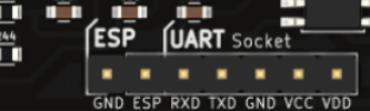 Figure 1: UART Interface in PSLab
 Figure 2: FTDI Module from


