I2C communication in PSLab Android

PSLab device is a compact electronic device with a variety of features. One of them is the ability to integrate sensors and get readings from them. One might think that why they should use PSLab device to get sensor readings and they can use some other hardware like Arduino. In those devices, user has to create firmware and need to know how to interface them with correct sampling rates and settings. But with PSLab, they all come in the whole package. User just have to plug the device to his phone and the sensor to device and he’s ready.

The idea of this blog post is to show how this sophisticated process is actually happening. Before that, let me give you a basic introduction on how I2C communication protocol works. I2C protocol is superior to UART and SPI protocols as they are device limited or requires many wires. But with I2C, you can literally connect thousands of sensors with just 4 wires. These wires are labeled as follows;

  • VCC – Power line
  • GND – Ground line
  • SDA – Data line
  • SCL – Signal clock

It is required that the SDA and SCL lines need to be connected to VCC line using two pull up resistors. But that’s just hardware. Let’s move on to learn how I2C communicate.

Here there is this communicating concept called master and slave. To start communication, master issues a global signal like a broadcast to all the devices connected to SCL and SDA lines. This signal contains the address of the slave, master needs to address and get data from. If the slave received this call to him, he will pull down the SDA line to signal the master that he heard him and ready to communicate with him. Here communication means reading or writing data. Then the communication happens and the link between master and slave breaks giving opportunity to other masters and slaves.

One might think this is a slow process. But these signals are transmitted at high frequencies. In PSLab it is at 100 kHz and that is one millisecond.

PSLab library has a special class to handle I2C communication. That is

public class I2C {/**/}


Once this class is initiated, one has to call the start function to start communication. This method requires the address we wish to communicate with and the mode of operation stating if it is a read or write operation

public int start(int address, int rw) throws IOException {
   packetHandler.sendByte(commandsProto.I2C_HEADER);
   packetHandler.sendByte(commandsProto.I2C_START);
   packetHandler.sendByte((address << 1) | rw & 0xff);
   return (packetHandler.getAcknowledgement() >> 4);
}


Once the address is sent out, protocol requires us to stop and wait for acknowledgement.

public void wait() throws IOException {
   packetHandler.sendByte(commandsProto.I2C_HEADER);
   packetHandler.sendByte(commandsProto.I2C_WAIT);
   packetHandler.getAcknowledgement();
}


If there are no congestion in the lines such as reading from multiple devices, the acknowledgement will be instantaneous. Once that is complete, we can start communication either byte-wise or bulk-wise

public int send(int data) throws IOException {
   packetHandler.sendByte(commandsProto.I2C_HEADER);
   packetHandler.sendByte(commandsProto.I2C_SEND);
   packetHandler.sendByte(data);
   return (packetHandler.getAcknowledgement() >> 4);
}


As an example, reading sensor values at a given interval can be done using the following method call.

public ArrayList<Byte> read(int length) throws IOException {
   ArrayList<Byte> data = new ArrayList<>();
   for (int i = 0; i < length - 1; i++) {
       packetHandler.sendByte(commandsProto.I2C_HEADER);
       packetHandler.sendByte(commandsProto.I2C_READ_MORE);
       data.add(packetHandler.getByte());
       packetHandler.getAcknowledgement();
   }
   packetHandler.sendByte(commandsProto.I2C_HEADER);
   packetHandler.sendByte(commandsProto.I2C_READ_END);
   data.add(packetHandler.getByte());
   packetHandler.getAcknowledgement();
   return data;
}


Once we get the data bundle, either we can save them or display in a graph whatever the way it’s convenient.

Reference:

  1. https://en.wikipedia.org/wiki/I%C2%B2C

Continue ReadingI2C communication in PSLab Android

Using external UART modules to debug PSLab operations

Pocket Science Lab by FOSSASIA is a compact tool that can be used for circuit analytics and debugging. To make things more interesting, this device can be accessed via the user interface using an Android app or also a desktop app. Both these apps use the UART protocol (Universal Asynchronous Receiver-Transmitter) to transmit commands to the PSLab device from mobile phone or PC and receive commands vice versa. The peculiar thing about hardware is that the developer cannot simply log data just like developing and debugging a software program. He needs some kind of an external mechanism or a tool to visualize those data packets travelling through the wires.

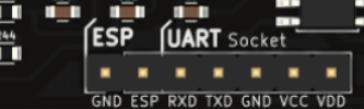
Figure 1: UART Interface in PSLab

PSLab has a UART interface extracted out simply for this reason and also to connect external sensors that use the UART protocol. With this, a developer who is debugging any of the Android app or the desktop app can view the command and data packets transmitted between the device and the user end application.

This  requires some additional components. UART interface has two communication related pins: Rx(Receiver) and Tx(Transmitter). We will need to monitor both these pin signals for input and output data packets. It should be kept in mind that PSLab is using 3.3V signals. This voltage level is important to mention here because if someone uses 5V signals on these pins, it will damage the main IC. There are FTDI modules available in market. FTDI stands for Future Technology Devices International which is a company name and their main product is this USB transceiver chip. These chips play a major role in electronic industry due to product reliability and multiple voltage support. PSLab uses 3.3V USB Tx Rx pins and modules other than FTDI wouldn’t support it.

Figure 2: FTDI Module from SparkFun

The module shown in Fig.2 is a FTDI module which you can simply plug in to computer and have a serial monitor interface. There are cheaper versions in shopping websites like eBay or Alibaba and they will also work fine. Both Tx and Rx pins will require two of these modules and connectivity is as follows;

PSLab [Rx Pin] → FTDI Module 1 [Rx Pin]
PSLab [Tx Pin] → FTDI Module 2 [Rx Pin]

This might look strange because everywhere we see a UART module is connected Rx → Tx and Tx → Rx. Notice that our idea is to monitor data packets. Not communicate with PSLab device directly. We want to see if our mobile phone Android app is sending correct commands to PSLab device or not and if PSLab device is transmitting back the expected result or not. This method helped a lot when debugging resistance measurement application in PSLab Android app.

Monitoring these UART data packets can be done simply using a serial monitor. You can either download and install some already built serial monitors or you can simply write a python script as follows which does the trick.

import serial

ser = serial.Serial(
    port='/dev/ttyUSB1',
    baudrate=1000000000
)

ser.isOpen()
while 1 :
    data = ''
    while ser.inWaiting() > 0:
        data += ser.read(1)

    if data != '':
        print ">>" + data

Once you are getting commands and responses, it will look like debugging a software using console.

References:

  1. PySerial Library : http://pyserial.readthedocs.io/en/latest/shortintro.html
  2. UART Protocol : https://en.wikipedia.org/wiki/Universal_asynchronous_receiver-transmitter
  3. FTDI : https://en.wikipedia.org/wiki/FTDI

Continue ReadingUsing external UART modules to debug PSLab operations

Communication by pySerial python module in PSLab

In the PSLab Desktop App we use Python for communication between the PC and PSLab device. The PSLab device is connected to PC via USB cable. The power for the hardware device is provided by the host through USB which in this case is a PC. We need well structured methods to establish communication between PC and PSLab device and this is where pySerial module comes in. We will discuss how to communicate efficiently from PC to a device like PSLab itself using pySerial module.

How to read and write data back to PSLab device?

pySerial is a python module which is used to communicate serially with microcontroller devices like Arduino, RaspBerry Pi, PSLab (Pocket Science Lab), etc. Serial data transfer is easier using this module, you just need to open a port and obtain serial object, which provides useful and powerful functionality. Users can send string (which is an array of bytes) or any other data type all data types can be expressed as byte string using struct module in python, read a specific number of bytes or read till some specific character like ‘\n’ is encountered. We are using this module to create custom read and write functions.

How to Install pySerial and obtain serial object for communication?

You can install pySerial using pip by following command

pip install pyserial

Once it’s installed we can now import it in our python script for use.

Obtain Serial Object

In Linux

>>> import serial
>>> ser = serial.Serial(‘/dev/ttyUSB0’)

In Windows

>>> ser = serial.Serial()
>>> ser.baudrate = 19200
>>> ser.port = ‘COM1’

Or

>>> ser = serial.Serial(‘COM1’, 19200)

You can specify other properties like timeout, stopbits, etc to Serial constructor.

Complete list of parameters is available here. Now this “ser” is an object of Serial class that provides all the functionalities through its interface. In PSLab we obtain a serial object and implement custom methods to handle communication which isn’t directly provided by pySerial, for example if we need to implement a function to get the version of the PSLab device connected. Inside the version read function we need to send some bytes to the device in order to obtain the version string from device as a byte response.

What goes under the hood?

We send some sequence of bytes to PSLab device, every sequence of bytes corresponds to a unique function which is already written in device’s firmware. Device recognises the function and responses accordingly.

Let’s look at code to understand it better.

ser.write(struct.Struct(‘B’).pack(11))  #  Sends 11 as byte string
ser.write(struct.Struct(‘B’).pack(5))   #  Sends 5 as bytes string
x = ser.readline()                      #  Reads bytes until ‘\n’ is encountered   

To understand packing and unpacking using struct module, you can have a read at my other blog post Packing And Unpacking Data in JAVA in which I discussed packing and unpacking of data as byte strings and touched a bit on How it’s done in Python.  

You can specify how many bytes you want to read like shown in code below, which is showing and example for 100 bytes :

x = ser.read(100)

After your communication is complete you can simply close the port by:

ser.close()

Based on these basic interface methods more complex functions can be written to handle your specific needs. More details one how to implement custom methods is available at python-communication-library of PSLab which uses pySerial for communication between Client and PSLab device.

An example of custom read function is suppose I want to write a function to read an int from the device. int is of 2 bytes as firmware is written in C, so we read 2 bytes from device and unpack them in client side i.e on PC. For more such custom functions refer packet_handler.py of PSLab python communication library.

def getInt(self):
      “””
      reads two bytes from the serial port and
      returns an integer after combining them
      “””
      ss = ser.read(2)  # reading 2 bytes from serial object
      try:
          if len(ss) == 2:
              return CP.ShortInt.unpack(ss)[0]  # unpacking bytes to make int
      except Exception as ex:
          self.raiseException(ex, “Communication Error , Function : get_Int”)

Resources

Continue ReadingCommunication by pySerial python module in PSLab