Basics behind BJT and FET experiments in PSLab

A high school student in his curriculum; will come across certain electronics and electrical experiments. One of them related to semiconductor devices such as Bipolar Junction Transistors (BJTs) and Field Effect Transistors (FETs). PSLab device is capable of function as a waveform generator, voltage and current source, oscilloscope and multimeter. Using these functionalities one can design an experiment. This blog post brings out the basics one should know about the experiment and the PSLab device to program an experiment in the saved experiments section.

Channels and Sources in the PSLab Device

The PSLab device has three pins dedicated to function as programmable voltage sources (PVS) and one pin for programmable current source (PCS).

Programmable Voltage Sources can generate voltages as follows;

  • PV1 →  -5V ~ +5V
  • PV2 → -3.3V ~ +3.3V
  • PV3 → 0 ~ +3.3V

Programmable Current Source (PCS) can generate current as follows;

  • PCS → 0 ~ 3.3mA

The device has 4 channel oscilloscope out of those CH1, CH2 and CH3 pins are useful in experiments of the current context type.

About BJTs and FETs

Every semiconductor device is made of Silicon(Si). Some are made of Germanium(Ge) but they are not widely used. Silicon material has a potential barrier of 0.7 V among P type and N type sections of a semiconductor device. This voltage value is really important in an experiment as in some practicals such as “BJT Amplifier”, there is no use of a voltage value setting below this value. So the experiment needs to be programmed to have 0.7V as the minimum voltage for Base terminal.

Basic BJT experiments

BJTs have three pins. Collector, Emitter and Base. Current to the Base pin will control the flow of electrons from Emitter to Collector creating a voltage difference between Collector and Emitter pins. This scenario can be taken down to three types as;

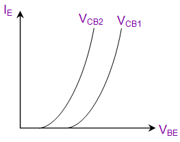
  • Input Characteristics → Relationship between Emitter current to VBE(Base to Emitter)
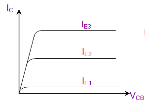
  • Output Characteristics → Relationship between IC(Collector) to VCB(Collector to Base)
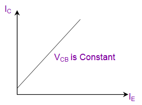
  • Transfer Characteristics → Relationship between IC(Collector) to IE(Emitter)

Input Characteristics

Output Characteristics

Transfer Characteristics


Basic FET experiments

FETs have three pins. Drain, Source and Gate. Voltage to Gate terminal will control the electron flow from either direction from or to Source and Drain. This scenario results in two types of experiments;

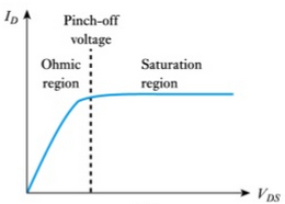
  • Output Characteristics → Drain current to Drain to Source voltage difference
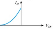
  • Transfer Characteristics → Gate to Source voltage to Drain current
Output Characteristics Transfer Characteristics

Using existing methods in PSLab android repository

Current implementation of the android application consists of all the methods required to read voltages and currents from the relevant pins and fetch waveforms from the channel pins and output voltages from PVS pins.

ScienceLab.java class – This class implements all the methods required for any kind of an experiment. The methods that will be useful in designing BJT and FET related experiments are;

Set Voltages

public void setPV1(float value);

public void setPV2(float value);

public void setPV3(float value);

Set Currents

public void setPCS(float value);

Read Voltages

public double getVoltage(String channelName, Integer sample);

Read Currents

To read current there is no direct way implemented. The current flow between two nodes can be calculated using the PVS pin value and the voltage value read from the channel pins. It uses Ohm’s law to calculate the value using the known resistance between two nodes.

In the following schematic; the collector current can be calculated using known PV1 value and the measured CH1 value as follows;

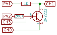
IC = (PV1 – CH1) / 1000

This is how it is actually implemented in the existing experiments.

If one needs to implement a new experiment of any kind, these are the basics need to know. There can be so many new experiments implemented using these basics. Some of them could be;

  • Effect of Temperature coefficient in Collector current
  • The influence in β factor in Collector current

Resources:

Continue ReadingBasics behind BJT and FET experiments in PSLab

Implementing Tree View in PSLab Android App

When a task expands over sub tasks, it can be easily represented by a stem and leaf diagram. In the context of android it can be implemented using an expandable list view. But in a scenario where the subtasks has mini tasks appended to it, it is hard to implement it using the general two level expandable list views. PSLab android application supports many experiments to perform using the PSLab device. These experiments are divided into major sections and each experiments are listed under them.

The best way to implement this functionality in the android application is using a multi layer treeview implementation. In this context three layers are enough as follows;


This was implemented with the help from a library called AndroidTreeView. This blog will outline how to modify and implement it in PSLab android application.

Basic Idea

Tree view implementation simply follows the data structure “Tree” used in algorithms. Every tree has a root where it starts and from the root there will be branches which are connected using edges. Every edge will have a parent and child. To reach a child, one has to traverse through only one route.

Setting Up Dependencies

Implementing tree view begins with setting up dependencies in the gradle file in the project.

compile 'com.github.bmelnychuk:atv:1.2.+'

Creating UI for tree view

The speciality about this implementation is that it can be loaded into any kind of a layout such as a linearlayout, relativelayout, framelayout etc.

final TreeNode Root = TreeNode.root();
Root.addChildren(
       // Add child nodes here
);
// Set up the tree view
AndroidTreeView experimentsListTree = new AndroidTreeView(getActivity(), Root);
experimentsListTree.setDefaultAnimation(true);
[LinearLayout/RelativeLayout].addView(experimentsListTree.getView());

Creating a node holder

Trees are made of a collection of tree nodes. A holder for a tree node can be created using an object which extends the BaseNodeViewHolder class provided by the library. BaseNodeViewHolder requires a holder class which is generally static so that it can be accessed without creating an instance which nests textviews, imageviews and buttons.

Once the holder extends the BaseNodeViewHolder, it should override two methods as follows;

@Override
public View createNodeView(final TreeNode node, ClassContainingNodeData header) {

}

@Override
public void toggle(boolean active) {

}

createNodeView() which inflate the view and toggle() method which can be used to toggle clicks on the tree node in the UI.

The following code snippet shows how to create an object which extends the above mentioned class with the overridden methods.

public class ExperimentHeaderHolder extends TreeNode.BaseNodeViewHolder<ExperimentHeaderHolder.ExperimentHeader> {

    private ImageView arrow;

    public ExperimentHeaderHolder(Context context) {
            super(context);
    }

    @Override
    public View createNodeView(final TreeNode node, ExperimentHeader header) {

            final LayoutInflater inflater = LayoutInflater.from(context);
            final View view = inflater.inflate(R.layout.header_holder, null, false);

            TextView title = (TextView) view.findViewById(R.id.title);
            title.setText(header.title);

            arrow = (ImageView) view.findViewById(R.id.experiment_arrow);
        
            return view;
    }

    @Override
    public void toggle(boolean active) {
            arrow.setImageResource(active ? arrow_drop_up : arrow_drop_down);
    }

    public static class ExperimentHeader {

            public String title;

            public ExperimentHeader(String title) {
               this.title = title;
            }
    }
}

Creating a TreeNode

Once the holder is complete, we can move on to creating an actual tree node. TreeNode class requires an object which extends the BaseNodeViewHolder class as mentioned earlier. Also it requires a viewholder which it can use to inflate the view in the tree layout. The viewholder can be a different class. The importance of this different implementation can be explained as follows;

TreeNode treeNode = new TreeNode(new ExperimentHeaderHolder.ExperimentHeader(“Title”))
       .setViewHolder(new ExperimentHeaderHolder(context));

In the Saved Experiments section of PSLab android application, all the three levels shouldn’t implement the toggle behavior as a user clicks on the experiment (last level item), he doesn’t expect the icon to change like the ones in headers where an arrow points up and down when he clicks on it. In this case we can reuse a holder which has the title attribute while creating only a holder which does not override the toggle function to ignore icon toggling at the last level of the tree view. This explanation can be illustrated using a code snippet as follows;

new TreeNode(new ExperimentHeaderHolder.ExperimentHeader(“Title”))
       .setViewHolder(new IndividualExperimentHolder(context));

Creating parent nodes and finally the Root node

The final part of the implementation is to create parent nodes to group up similar experiments together. The TreeNode object supports a method call addChild() and addChildren(). addChild() method allows adding one tree node to the specific tree node and addChildren() method allows adding many tree nodes at the same time. Following code snippet illustrates how to add many tree nodes to a node and make it a parent node.

treeDiodeExperiments.addChildren(treeZener, treeDiode, treeDiodeClamp, treeDiodeClip, treeHalfRectifier, treeFullWave);

Setting a click listener

Click listener is a very important implementation. Each tree node can be attached with a click listener using the interface provided by the library as follows;

treeNode.setClickListener(new TreeNode.TreeNodeClickListener() {
   @Override
   public void onClick(TreeNode node, Object value) {

   }
});

The value object is the class attached to the holder and its attributes can be retireved by casting it to the specific class using casting methods;

String title = ((ExperimentHeaderHolder.ExperimentHeader) value).title;

Resources:

Continue ReadingImplementing Tree View in PSLab Android App

Integrating Stock Sensors with PSLab Android App

A sensor is a digital device (almost all the time an integrated circuit) which can receive data from outer environment and produce an electric signal proportional to that. This signal will be then processed by a microcontroller or a processor to provide useful functionalities. A mobile device running Android operating system usually has a few sensors built into it. The main purpose of these sensors is to provide user with better experience such as rotating the screen as he moves the device or turn off the screen when he is making a call to prevent unwanted screen touch events. PSLab Android application is capable of processing inputs received by different sensors plugged into it using the PSLab device and produce useful results. Developers are currently planning on integrating the stock sensors with the PSLab device so that the application can be used without the PSLab device.

This blog is about how to initiate a stock sensor available in the Android device and get readings from it. Sensor API provided by Google developers is really helpful in achieving this task. The process is consist of several steps. It is also important to note the fact that there are devices that support only a few sensors while some devices will support a lot of sensors. There are few basic sensors that are available in every device such as

  • “Accelerometer” – Measures acceleration along X, Y and Z axis
  • “Gyroscope” – Measures device rotation along X, Y and Z axis
  • “Light Sensor” – Measures illumination in Lux
  • “Proximity Sensor” – Measures distance to an obstacle from sensor

The implementing steps are as follows;

  1. Check availability of sensors

First step is to invoke the SensorManager from Android system services. This class has a method to list all the available sensors in the device.

SensorManager sensorManager;
sensorManager = (SensorManager) getSystemService(Context.SENSOR_SERVICE);
List<Sensor> sensors = sensorManager.getSensorList(Sensor.TYPE_ALL);

Once the list is populated, we can iterate through this to find out if the required sensors are available and obstruct displaying activities related to sensors that are not supported by the device.

for (Sensor sensor : sensors) {
   switch (sensor.getType()) {
       case Sensor.TYPE_ACCELEROMETER:
           break;
       case Sensor.TYPE_GYROSCOPE:
           break;
       ...
   }
}

  1. Read data from sensors

To read data sent from the sensor, one should implement the SensorEventListener interface. Under this interface, there are two method needs to be overridden.

public class StockSensors extends AppCompatActivity implements SensorEventListener {

    @Override
    public void onSensorChanged(SensorEvent sensorEvent) {

    }

    @Override
    public void onAccuracyChanged(Sensor sensor, int i) {

    }
}

Out of these two methods, onSensorChanged() method should be addressed. This method provides a parameter SensorEvent which supports a method call getType() which returns an integer value representing the type of sensor produced the event.

@Override
public void onSensorChanged(SensorEvent sensorEvent) {
   switch (sensorEvent.sensor.getType()) {
       case Sensor.TYPE_ACCELEROMETER:
           break;
       case Sensor.TYPE_GYROSCOPE:
           break;
       ...
   }
}

Each available sensor should be registered under the SensorEventListener to make them available in onSensorChanged() method. The following code block illustrates how to modify the previous code to register each sensor easily with the listener.

for (Sensor sensor : sensors) {
   switch (sensor.getType()) {
       case Sensor.TYPE_ACCELEROMETER:
           sensorManager.registerListener(this, sensorManager.getDefaultSensor(Sensor.TYPE_ACCELEROMETER), SensorManager.SENSOR_DELAY_UI);
           break;
       case Sensor.TYPE_GYROSCOPE:
           sensorManager.registerListener(this, sensorManager.getDefaultSensor(Sensor.TYPE_GYROSCOPE), SensorManager.SENSOR_DELAY_UI);
           break;
   }
}

Depending on the readings we can provide user with numerical data or graphical data using graphs plotted using MPAndroidChart in PSLab Android application.

The following images illustrate how a similar implementation is available in Science Journal application developed by Google.

Resources

Continue ReadingIntegrating Stock Sensors with PSLab Android App

Handling graph plots using MPAndroid chart in PSLab Android App

In PSLab Android App, we expose the Oscilloscope and Logic Analyzer functionality of PSLab hardware device. After reading data-points to plot, we need to show plot data on graphs for better understanding and visualisation. Sometimes we need to save graphs to show output/findings of the experiment. Hence we will be using MPAndroidChart library to plot and save graphs as it provides a nice and clean methods to do so.

First add MPAndroid Chart as dependency in your app build.gradle to include the library

dependencies {
 compile 'com.github.PhilJay:MPAndroidChart:v3.0.2'
}

For chart view in your layout file, there are many available options like Line Chart, Bar Chart, Pie Chart, etc. For this post I am going to use Line Chart.

Add LineChart in your layout file

<com.github.mikephil.charting.charts.LineChart
        android:id="@+id/lineChart"
        android:layout_width="match_parent"
        android:layout_height="match_parent" />

Take a reference to LineChart of layout file in your Activity/Fragment

LineChart lineChart = (LineChart) findViewById(R.id.chart);// Activity
LineChart lineChart = (LineChart) view.findViewById(R.id.chart);// Fragment

Now we add dataset to LineChart of layout file, I am going to add data for two curves sine and cosine function to plot sine and cosine wave on LineChart. We create two different LineDataSet one for the sine curve entries and other for the cosine curve entries.

List <Entry> sinEntries = new ArrayList<>(); // List to store data-points of sine curve 
List <Entry> cosEntries = new ArrayList<>(); // List to store data-points of cosine curve

// Obtaining data points by using Math.sin and Math.cos functions
for( float i = 0; i < 7f; i += 0.02f ){
sinEntries.add(new Entry(i,(float)Math.sin(i)));
cosEntries.add(new Entry(i,(float)Math.cos(i)));
}

List<ILineDataSet> dataSets = new ArrayList<>(); // for adding multiple plots

LineDataSet sinSet = new LineDataSet(sinEntries,"sin curve");
LineDataSet cosSet = new LineDataSet(cosEntries,"cos curve");

// Adding colors to different plots 
cosSet.setColor(Color.GREEN);
cosSet.setCircleColor(Color.GREEN);
sinSet.setColor(Color.BLUE);
sinSet.setCircleColor(Color.BLUE);

// Adding each plot data to a List
dataSets.add(sinSet);
dataSets.add(cosSet);

// Setting datapoints and invalidating chart to update with data points
lineChart.setData(new LineData(dataSets));
lineChart.invalidate();

After adding datasets to chart and invalidating it, chart is refreshed with the data points which were added in dataset.

After plotting graph output would look like the image below:

You can change the dataset and invalidate chart to update it with latest dataset.

To save graph plot, make sure you have permission to write to external storage, if not add it into your manifest file

<manifest ...>
    <uses-permission android:name="android.permission.WRITE_EXTERNAL_STORAGE" />
    ...
</manifest>

To save the photo of chart into Gallery:

lineChart.saveToGallery("title");

To save a some specific location:

lineChart.saveToPath("title", "Location on SD Card");

If you want to do some resizing in chart or save two three charts in a single image, you can do so by taking out the Bitmaps and processing them to meet your requirements:

lineChart.getChartBitmap();

Resources

Continue ReadingHandling graph plots using MPAndroid chart in PSLab Android App

Creating Multiple Device Compatible Layouts in PSLab Android

The developer’s goal is that PSLab Android App as an app should run smoothly on all the variety of Android devices out in the market. There are two aspects of it – the app should be able to support maximum number of Android versions possible which is related to the core software part and the other being the app should be able to generate the same user experience on all sizes of screens. This post focuses on the later.

There are a whole range of android devices available in the market right from 4 inch mobile phones to 12 inch tablets and the range in the screen sizes is quite large. So, the challenge in front of app designers is to make the app compatible with the maximum  number of devices without doing any specific tweaks related to a particular resolution range. Android has its mechanism of scaling the app as per the screen size and it does a good job almost all the time, however, still there are cases where android fails to scale up or scale down the app leading to distorted layout of the app.

This blog discusses some of the tricks that needs to be kept in mind while designing layouts that work independent of screen sizes.

Avoid using absolute dimensions

It is one of the most common things to keep in mind before starting any UI design. Use of absolute dimensions like px, inch etc. must be avoided every time as they are fixed in size and don’t scale up or scale down while screen sizes are changed. Instead relative dimensions like dp should be used which depend on the resolution and scale up or scale down. ( It’s a fair assumption that bigger screens will have better resolution compared to the smaller ones although exceptions do exist) .

Ensure the use of correct layout/View group

Since, android provides a variety of layouts like Linearlayout, Constrainedlayout, Relativelayout, Tablelayout and view groups like ScrollView, RecyclerView, ListView etc. it is often confusing to know which layout/viewgroup should be used. The following list gives a rough idea of when to use a particular layout or view group.

  • Linearlayout – Mostly used for simple designs when the elements are stacked in ordered horizontal/vertical fashion and it needs explicit declaration of orientation.
  • Relativelayout – Mostly used when the elements need to defined relative to the parent or the neighbouring elements. Since, the elements are relative, there is no need to define the orientation.
  • Constraintlayout – It has all the features of Relativelayout and in addition a feature of adding constraints to the child elements or neighbouring elements.
  • Tablelayout – Tablelayout is helpful to when all the views/widgets are arranged in an ordered fashion.

All the above layouts can be used interchangeably most of the times, however, certain cases make some more favourable than others like when than views/ widgets are not present in an organised manner, it is better to stick to Linearlayout or Relativelayout.

  • ListView – Used when the views/ widgets in a screen are repeated, so using a listview ensures that the volume of the code is reduced and all the repetitive views are identical in nature.
  • RecyclerView – More of an improved version of ListView. It is recommended to use this view over ListView. Additionally this view group supports features like swipe to refresh.
  • ScrollView – Used when the UI screen cannot fit within the given screen space. ScrollView supports one direct child layout. So, to implement a scrollview, all the views must be under a particular layout and then masked by scrollview.

Choosing the correct layout or view group would help to create a better UI.

Use of layout_weight

Ensuring the layout width assigned in XML file covers the entire width on the screen. For ensuring this, one possible solution is to use layout_weight instead of layout_width.

Example –

<TextView
   android:id="@+id/tv_control_read9"
   android:layout_width="0dp"
   android:layout_weight="1"
   android:layout_height="30dp"
   android:layout_marginTop="10dp"
/>


In order to use layout_weight, layout_width must be set to 0 else it would interfere with the width and as layout_width is a compulsory parameter it cannot be omitted. Layout weight can be any number and the space is allocated to each view in proportion to the weights assigned. Since it does not involve numerical dimensions, the distribution would be uniform for all types of screens. The result is clearly evident here. The same UI in different screen sizes is displayed below.

blog_post_8_2

Fig: Screenshot taken on a 6” phone and on a 4” phone. Although the screen area of 4” phone is 44% that of the 6” phone, the UIs are identically the same.

Create different layout directories for different resolutions

  • Creating different layouts for different screen sizes ensures that the limitations of smaller screen sizes are taken care of and the advantages offered by bigger screen sizes are put to the best use.
  • The Android documentation here mentions the conventions to be followed while designing.
  • Although over the years, android has become better at auto-adjusting layouts for different screen sizes. However, if the no. of views and widgets are high, auto-adjusting does not work well as in case of PSLab and it is better to create different sets of layouts.
  • As evident from the picture of the 8” tablet, although the auto-adjusted layout is manageable, the layout looks stretched and does not utilize the entire screen space, so it a better UI can be made by creating a dedicated layout directory for bigger screens.

Additional resources


Continue ReadingCreating Multiple Device Compatible Layouts in PSLab Android

Using Sensors with PSLab Android App

The PSLab Android App as of now supports quite a few sensors. Sensors are an essential part of many science experiments and therefore PSLab has a feature to support plug & play sensors. The list of sensors supported by PSLab can be found here.

  • AD7718 – 24-bit 10-channel Low voltage Low power Sigma Delta ADC
  • AD9833 – Low Power Programmable Waveform generator
  • ADS1115 – Low Power 16 bit ADC
  • BH1750 – Light Intensity sensor
  • BMP180 – Digital Pressure Sensor
  • HMC5883L – 3-axis digital magnetometer
  • MF522 – RFID Reader
  • MLX90614 – Infrared thermometer
  • MPU6050 – Accelerometer & gyroscope
  • MPU925x – Accelerometer & gyroscope
  • SHT21 – Humidity sensor
  • SSD1306 – Control for LED matrix
  • Sx1276 – Low Power Long range Transceiver
  • TSL2561 – Digital Luminosity Sensor

All the sensors except Sx1276 communicate using the I2C protocol whereas the Sx1276 uses the SPI protocol for communication. There is a dedicated set of ports on the PSLab board for the communication under the label I2C with the ports named 3.3V, GND, SCL & SDA.

blog_post_7_1

Fig; PSLab board sketch

Any I2C sensor has ports named 3.3V/VCC, GND, SCL, SDA at least along with some other ports in some sensors. The connections are as follows:

  1. 3.3V on PSLab – 3.3V/VCC on sensor
  2. GND on PSLab – GND on sensor
  3. SCL on PSLab – SCL on sensor
  4. SDA on PSLab – SDA on sensor

The diagram here shows the connections

For using the sensors with the Android App, there is a dedicated I2C library written in communication in Java for the communication. Each sensor has its own specific set of functionalities and therefore has its own library file. However, all these sensors share some common features like each one of them has a getRaw method which fetches the raw sensor data. For getting the data from a sensor, the sensor is initially connected to the PSLab board.

The following piece of code is responsible for detecting any devices that are connected to the PSLab board through the I2C bus. Each sensor has it’s own unique address and can be identified using it. So, the AutoScan function returns the addresses of all the connected sensors and the sensors can be uniquely identified using those addresses.

public ArrayList<Integer> scan(Integer frequency) throws IOException {
	if (frequency == null) frequency = 100000;
	config(frequency);
	ArrayList<Integer> addresses = new ArrayList<>();
	for (int i = 0; i < 128; i++) {
		int x = start(i, 0);
		if ((x & 1) == 0) {
			addresses.add(i);
		}
		stop();
	}
	return addresses;
}


As per the addresses fetched, the sensor library corresponding to that particular sensor can be imported and the getRaw method can be called. The getRaw method will return the raw sensor data. For example here is the getRaw method of ADS1115.

public int[] getRaw() throws IOException, InterruptedException {
	String chan = typeSelection.get(channel);
	if (channel.contains("UNI"))
		return new int[]{(int) readADCSingleEnded(Integer.parseInt(chan))};
	else if (channel.contains("DIF"))
		return new int[]{readADCDifferential(chan)};
	return new int[0];
}

Here the raw data is returned in the form of voltages in mV.

Similarly, the other sensors return some values like luminosity sensor TSL2561 returns values of luminosity in Lux, the accelerometer & gyroscope MPU6050 returns the angles of the 3-axes.

In order to initiate the process of getting raw data from the sensor in Sensor Activity, the object for the sensor is created and the method of getRaw is called. The following is the implementation for ADS1115. The rest of the sensors also have an implementation similar to this. There are try-catch statements in the code to handle some of the exceptions thrown during process of method calls.

ADS1115 ADS1115 = null;
try {
	ADS1115 = new ADS1115(i2c);
} catch (IOException | InterruptedException e) {
	e.printStackTrace();
}

int[] dataADS1115 = null;
String datadispADS1115 = null;
try {
	if (ADS1115 != null) {
		dataADS1115 = ADS1115.getRaw();
	}
} catch (IOException | InterruptedException e) {
	e.printStackTrace();
}

if (dataADS1115 != null) {
	for(int i = 0; i < dataADS1115.length; i++)
		datadispADS1115 += String.valueOf(dataADS1115[i]);
	}

tvSensorGetRaw.setText(datadispADS1115);


Additional Resources

  1. Sensor implementation in PSLab Python repository – https://github.com/fossasia/pslab-python/tree/development/PSL/SENSORS
  2. Using the sensors with Arduino in case you have worked with Arduino before – The basic connections are same as PSLab http://www.instructables.com/id/Arduino-MPU-6050-Getting-It-to-Work/

Continue ReadingUsing Sensors with PSLab Android App

Creating Custom Components in the PSLab Android App

PSLab Android App supports a lot of features and each of these features need components & views for their implementation. A typical UI of PSLab is shown in the figure below. Considering the number of views & components used in the figure, implementation of each view & component separately would lead to a huge volume of repetitive and inefficient code. As it is evident that the EditText and two buttons beside it keep repeating a lot, it is wiser to create a single custom component consisting of an EditText and two buttons. This not only leads to efficient code but also results in a drastic reduction of the volume of code.

Android has a feature which allows creating components. For almost all the cases, the pre-defined views in Android serve our purpose of creating the UIs. However, sometimes there is a need to create custom components to reduce code volume and improve quality. Custom components are used when a particular set of component needed by us is not present in the Android view collection or when a pattern of components is frequently repeated or when we need to reduce the code complexity.

The above set can be replaced by defining a custom component which includes an edittext and two buttons and then treating it like just any other component. To get started with creating a custom component, the steps are the following:

Create a layout for the custom component to be designed

<?xml version="1.0" encoding="utf-8"?>
<LinearLayout xmlns:android="http://schemas.android.com/apk/res/android"
   android:orientation="horizontal" android:layout_width="match_parent"
   android:layout_height="match_parent">

   <Button
       android:id="@+id/button_control_plus"
       android:layout_width="0dp"
       android:layout_weight="0.5"
       android:layout_height="20dp"
       android:background="@drawable/button_minus" />

   <EditText
       android:id="@+id/edittext_control"
       android:layout_width="0dp"
       android:layout_weight="2"
       android:layout_height="24dp"
       android:layout_marginTop="@dimen/control_margin_small"
       android:inputType="numberDecimal"
       android:padding="@dimen/control_edittext_padding"
       android:background="@drawable/control_edittext" />

   <Button
       android:id="@+id/button_control_minus"
       android:layout_width="0dp"
       android:layout_weight="0.5"
       android:layout_height="20dp"
       android:background="@drawable/button_plus" />
</LinearLayout>

The layout file edittext_control.xml is created with three views and each one of them has been assigned an ID along with all the other relevant parameters.

Incorporate the newly created custom layout in the Activity/Fragment layout file

<org.fossasia.pslab.others.Edittextwidget
       android:id="@+id/etwidget_control_advanced1"
       android:layout_height="wrap_content"
       android:layout_width="0dp"
       android:layout_weight="2"
       android:layout_marginLeft="@dimen/control_margin_small"
       android:layout_marginStart="@dimen/control_margin_small"
/>

The custom layout can be added the activity/fragment layout just like any other view and can be assigned properties similarly.

Create the activity file for the custom layout

public class Edittextwidget extends LinearLayout{

   private EditText editText;
   private Button button1;
   private Button button2;
   private double leastCount;
   private double maxima;
   private double minima;

 
   public Edittextwidget(Context context, AttributeSet attrs, int defStyle) {
       super(context, attrs, defStyle);
       applyAttrs(attrs);
   }

   public Edittextwidget(Context context, AttributeSet attrs) {
       super(context, attrs);
       applyAttrs(attrs);
   }

   public Edittextwidget(Context context) {
       super(context);
   }

  public void init(Context context, final double leastCount, final double minima, final double maxima) {
       View.inflate(context, R.layout.edittext_control, this);
       editText = (EditText) findViewById(R.id.edittext_control);
       button1 = (Button) findViewById(R.id.button_control_plus);
       button2 = (Button) findViewById(R.id.button_control_minus);

       button1.setOnClickListener(new OnClickListener() {
           @Override
           public void onClick(View v) {
               Double data = Double.valueOf(editText.getText().toString());
               data = data - leastCount;
               data = data > maxima ? maxima : data;
               data = data < minima ? minima : data;
               editText.setText(String.valueOf(data));
           }
       });

       button2.setOnClickListener(new OnClickListener() {
           @Override
           public void onClick(View v) {
               Double data = Double.valueOf(editText.getText().toString());
               data = data + leastCount;
               data = data > maxima ? maxima : data;
               data = data < minima ? minima : data;
               editText.setText(String.valueOf(data));
           }
       });
   }

   private void applyAttrs(AttributeSet attrs) {
       TypedArray a = getContext().obtainStyledAttributes(attrs, R.styleable.Edittextwidget);
       final int N = a.getIndexCount();
       for (int i = 0; i < N; ++i) {
           int attr = a.getIndex(i);
           switch (attr) {
               case R.styleable.Edittextwidget_leastcount:
                   this.leastCount = a.getFloat(attr, 1.0f);
                   break;
               case R.styleable.Edittextwidget_maxima:
                   this.maxima = a.getFloat(attr, 1.0f);
                   break;
               case R.styleable.Edittextwidget_minima:
                   this.minima = a.getFloat(attr, 1.0f);
           }
       }
       a.recycle();
   }
}

In the activity file Editextwidget.java, the views of the custom layout are defined and functionalities are assigned to them. For example, here there are two buttons which work as increment/decrement buttons and an edittext which takes numeric input. The buttons are initiated just like the way they are done in other activity/fragment using OnClickListener.

Define the attributes for the custom layout

<declare-styleable name="Edittextwidget">
     <attr name="leastcount" format="float" />
     <attr name="maxima" format="float" />
     <attr name="minima" format="float" />
</declare-styleable>

The attributes for the custom layout are defined in the attrs.xml file. Each attribute is assigned a name and a format which can be int, float, double, string etc.

Finally call the methods of the custom layout from the desired activity/fragment

Edittextwidget etwidgetControlAdvanced1 = (Edittextwidget)view.findViewById(R.id.etwidget_control_advanced1);

etwidgetControlAdvanced1.init(getContext(), 1.0, 10.0, 5000.0);

The init method of Edittextwidget.java is called while passing the relevant parameters like context, least count, maxima and minima.

Additional Resources on Custom Components

  1. Official Android Guide on Custom components – https://developer.android.com/guide/topics/ui/custom-components.html
  2. Simple example of creating a custom component to get started – https://www.tutorialspoint.com/android/android_custom_components.htm
Continue ReadingCreating Custom Components in the PSLab Android App

Trigger Controls in Oscilloscope in PSLab

PSLab Desktop App has a feature of oscilloscope. Modern day oscilloscopes found in laboratories support a lot of advanced features and addition of trigger controls in oscilloscope was one such attempt in adding an advanced feature in the oscilloscope. As the current implementation of trigger is not robust enough, this feature would help in better stabilisation of waveforms.

Captured waveforms often face the problem of distortion and trigger helps to solve this problem. Trigger in oscilloscope is an essential feature for signal characterisation.  as it synchronises the horizontal sweep of the oscilloscope to the proper point of the signal. The trigger control enables users to stabilise repetitive waveforms as well as capture single-shot waveforms. By repeatedly displaying similar portion of the input signal, the trigger makes repetitive waveform look static. In order to visualise how an oscilloscope looks with or without a trigger see the following figures below.

blog_post_5_1

blog_post_5_2

Fig 1: (a) Without trigger  (b) With trigger

The Fig:1(a) is the actual waveform received by the oscilloscope and it can be easily noticed that interpreting it is confusing due to the overlapping of multiple waveforms together. So, in Fig:1(b) the trigger control stabilises the waveforms and captures just one waveform.

In general the commonly used trigger modes in laboratory oscilloscopes are:-

  • Auto – This trigger mode allows the oscilloscope to acquire a waveform even when it does not detect a trigger condition. If no trigger condition occurs while the oscilloscope waits for a specific period (as determined by the time-base setting), it will force itself to trigger.
  • Normal – The Normal mode allows the oscilloscope to acquire a waveform only when it is triggered. If no trigger occurs, the oscilloscope will not acquire a new waveform, and the previous waveform, if any, will remain on the display.
  • Single – The Single mode allows the oscilloscope to acquire one waveform each time you press the RUN button, and the trigger condition is detected.
  • Scan – The Scan mode continuously sweeps waveform from left to right.

Implementing Trigger function in PSLab

PSLab has a built in basic functionality of trigger control in the configure_trigger method in sciencelab.py. The method gets called when trigger is enabled in the GUI. The trigger is activated when the incoming wave reaches a certain voltage threshold and the PSLab also provides an option of either selecting the rising or falling edge for trigger. Trigger is especially useful in experiments handling waves like sine waves, square wave etc. where trigger helps to get a clear picture.

In order to initiate trigger in the PSLab desktop app, the configure_trigger method in sciencelab.py is called. The configure_trigger method takes some parameters for input but they are optional. If values are not specified the default values are assumed.

def configure_trigger(self, chan, name, voltage, resolution=10, **kwargs):
        
  prescaler = kwargs.get('prescaler', 0)
        try:
            self.H.__sendByte__(CP.ADC)
            self.H.__sendByte__(CP.CONFIGURE_TRIGGER)
            self.H.__sendByte__(
                (prescaler << 4) | (1 << chan))  
            if resolution == 12:
                level = self.analogInputSources[name].voltToCode12(voltage)
                level = np.clip(level, 0, 4095)
            else:
                level = self.analogInputSources[name].voltToCode10(voltage)
                level = np.clip(level, 0, 1023)

            if level > (2 ** resolution - 1):
                level = (2 ** resolution - 1)
            elif level < 0:
                level = 0

            self.H.__sendInt__(int(level))  # Trigger
            self.H.__get_ack__()
        
        except Exception as ex:
  	    self.raiseException(ex, "Communication Error , Function : " + inspect.currentframe().f_code.co_name)

The method takes the following parameters in the method call

  • chan – Channel . 0, 1,2,3. corresponding to the channels being recorded by the capture routine(not the analog inputs).
  • name – The name of the channel. ‘CH1’… ‘V+’.
  • voltage – The voltage level that should trigger the capture sequence(in Volts).

The similar feature will also be used in oscilloscope in the Android app with the code corresponding to this method  in ScienceLab written in Java.

Additional Resources

  1. Read more about Trigger here – http://www.radio-electronics.com/info/t_and_m/oscilloscope/oscilloscope-trigger.php
  2. Learn more about trigger modes in oscilloscopes – https://www.picotech.com/library/oscilloscopes/advanced-digital-triggers
  3. PSLab Python repository to know the underlying code – https://github.com/fossasia/pslab-python


Continue ReadingTrigger Controls in Oscilloscope in PSLab

Designing Control UI of PSLab Android using Moqups

Mockups are an essential part of app development cycle. With numerous mock-up tools available for android apps (both offline and online), choosing the right mock-up tool becomes quite essential. The developers need a tool that supports the latest features like drag & drop elements, support collaboration upto some extent and allow easy sharing of mockups. So, Moqups was chosen as the mockups tool for the PSLab Android team.

Like other mock-up tools available in the market, using moqups is quite simple and it’s neat & simple user interface makes the job easier. This blog discusses some of the important aspects that need to be taken care of while designing mockups.

A typical online mock-up tool would look like this having a palette to drag & drop UI elements like Buttons, Text boxes, Check boxes etc. Additionally a palette to modify the features of each element ( here on the right ) and other options at the top related to prototyping, previewing etc.

    • The foremost challenge while designing any mock-up is to keep the design neat and simple such that even a layman doesn’t face problems while using it. A simple UI is always appealing and the current trend of UIs is creating flat & crisp UIs.

    • For example, the above mock-up design has numerous advantages for both a user and also as a programmer. There are seek bars as well as text boxes to input the values along with the feature of displaying the value that actually gets implemented and it’s much simpler to use. From the developer’s perspective, presence of seven identical views allows code reuse. A simple layout can be designed for one functionality and since all of them are identical, the layout can be reused in a Recyclerview.
    • The above design is a portion of the Control UI which displays the functionalities for  using PSLab as a function generator and as a voltage/current source.

    • The other section of the UI is of the Read portion. This has the functionalities to measure various parameters like voltage, resistance, capacitance, frequency and counting pulses. Here, drop-down boxes have been provided at places where channel selection is required. Since voltages are most commonly measured values in any experiment, voltages of all the channels have been displayed simultaneously.
    • Attempts should always be made to keep the smaller views as identical as possible since it becomes easier for the developer to implement it and also for the user to understand.


The Control UI has an Advanced Section which has features like Waveform Generators allows to generate sine/square waves of a given frequency & phase, Configuring Pulse Width Modulation (PWM)  and selecting the Digital output channel. Since, the use of such features are limited to higher level experiments, they have been separately placed in the Advanced section.

Even here drop-down boxes, text boxes & check boxes have been used to make UI look interactive.

The common dilemma faced while writing the XML file is regarding the view type to be chosen as Android provides a lot of them like LinearLayout, ConstraintLayout, ScrollView, RecyclerView, ListView etc. So, although there are several possible ways of designing a view. Certain things like using ListView or RecyclerView where there is repetition of elements is easier and when the elements are quite distinct from each other, it is better to stick to LinearLayout and ConstraintLayout.

Continue ReadingDesigning Control UI of PSLab Android using Moqups

Using ButterKnife in PSLab Android App

ButterKnife is an Android Library which is used for View injection and binding. Unlike Dagger, ButterKnife is limited to views whereas Dagger has a much broader utility and can be used for injection of anything like views, fragments etc. Being limited to views makes it much more simpler to use compared to dagger.

The need for using ButterKnife in our project PSLab Android was felt due to the fact binding views would be much more simpler in case of layouts like that of Oscilloscope Menu which has multiple views in the form of Textboxes, Checkboxes, Seekbars, Popups etc. Also, ButterKnife makes it possible to access the views outside the file in which they were declared. In this blog, the use of ButterKnife is limited to activities and fragments.

ButterKnife can used anywhere we would have otherwise used findViewById(). It helps in preventing code repetition while instantiating views in the layout. The ButterKnife blog has neatly listed all the possible uses of the library.

The added advantage of using Butterknife are-

  • The hassle of using Boilerplate code is not needed and the code volume is reduced significantly in some cases.
  • Setting up ButterKnife is quite easy as all it takes is adding one dependency to your gradle file.
  • It also has other features like Resource Binding (i.e binding String, Color, Drawable etc.).
  • Other uses like simplification of code while using buttons. For example, there is no need of using findViewById and setOnClickListener, simple annotation of the button ID with @OnClick does the task.

Using butterknife was essential for PSLab Android since for the views shown below which has too many elements, writing boilerplate code can be a very tedious task.

Using ButterKnife in activities

The PSLab App defines several activities like MainActivity, SplashActivity, ControlActivity etc. each of which consists of views that can be injected with ButterKnife.

After setting up ButterKnife by adding dependencies in gradle files, import these modules in every activity.

import butterknife.BindView;
import butterknife.ButterKnife;

Traditionally, views in Android are defined as follows using the ID defined in a layout file. For this findViewById is used to retrieve the widgets.

private NavigationView navigationView;
private DrawerLayout drawer;
private Toolbar toolbar;

navigationView = (NavigationView) findViewById(org.fossasia.pslab.R.id.nav_view);
drawer = (DrawerLayout) findViewById(org.fossasia.pslab.R.id.drawer_layout);
toolbar = (Toolbar) findViewById(org.fossasia.pslab.R.id.toolbar);

However, with the use of Butterknife, fields are annotated with @BindView and a View ID for finding and casting the view automatically in the layout files.
After the annotation, finding and casting of views ButterKnife.bind(this) is called to bind the views in the corresponding activity.

@BindView(R.id.nav_view) NavigationView navigationView;
@BindView(R.id.drawer_layout) DrawerLayout drawer;
@BindView(R.id.toolbar) Toolbar toolbar;
setContentView(R.layout.activity_main);
ButterKnife.bind(this);

Using ButterKnife in fragments

The PSLab Android App implements ApplicationFragment, DesignExperimentsFragment, HomeFragment etc., so ButterKnife for fragments is also used.

Using ButterKnife is fragments is slightly different from using it in activities as the binded views need to be destroyed on leaving the fragment as the fragments have different life cycle( Read about it here). For this an Unbinder needs to be defined to unbind the views before they are destroyed.

Quoting from the official documentation

When binding a fragment in OnCreateView, set the views to null in OnDestroyView. Butter Knife returns an Unbinder instance when you call bind to do this for you. Call its unbind method in the appropriate lifecycle callback.

So, an additional module of ButterKnife is imported

import butterknife.BindView;
import butterknife.ButterKnife;
import butterknife.Unbinder;

Similar as that of activities, the code below can be replaced by the corresponding ButterKnife code.

TextView tvDeviceStatus = (TextView)view.findViewById(org.fossasia.pslab.R.id.tv_device_status);
TextView tvVersion = (TextView)view.findViewById(org.fossasia.pslab.R.id.tv_device_version);
ImageView imgViewDeviceStatus = (ImageView)view.findViewById(org.fossasia.pslab.R.id.img_device_status);
@BindView(R.id.tv_device_status) TextView tvDeviceStatus;
@BindView(R.id.tv_device_version) TextView tvVersion;
@BindView(R.id.img_device_status) ImageView imgViewDeviceStatus;
private Unbinder unbinder;

Additionally, the unbinder object is used to store the returned Unbinder instance when ButterKnife.bind is called for Fragments.

unbinder = ButterKnife.bind(this,view);

Finally, the unbind method of unbinder is called while view is destroyed.

@Override public void onDestroyView() {
super.onDestroyView();
unbinder.unbind();
}

Continue ReadingUsing ButterKnife in PSLab Android App