Implement Wave Generation Functionality in The PSLab Android App

The PSLab Android App works as an Oscilloscope using the audio jack of Android device. The implementation for the scope using in-built mic is discussed in the post Using the Audio Jack to make an Oscilloscope in the PSLab Android App. Another application which can be implemented by hacking the audio jack is Wave Generation. We can generate different types of signals on the wires connected to the audio jack using the Android APIs that control the Audio Hardware. In this post, I will discuss about how we can generate wave by using the Android APIs for controlling the audio hardware.

Configuration of Audio Jack for Wave Generation

Simply cut open the wire of a cheap pair of earphones to gain control of its terminals and attach alligator pins by soldering or any other hack(jugaad) that you can think of. After you are done with the tinkering of the earphone jack, it should look something like shown in the image below.

Source: edn.com

If your earphones had mic, it would have an extra wire for mic input. In any general pair of earphones the wire configuration is almost the same as shown in the image below.

Source: flickr

Android APIs for Controlling Audio Hardware

AudioRecord and AudioTrack are the two classes in Android that manages recording and playback respectively. For Wave Generation application we only need AudioTrack class.

Creating an AudioTrack object: We need the following parameters to initialise an AudioTrack object.

STREAM TYPE: Type of stream like STREAM_SYSTEM, STREAM_MUSIC, STREAM_RING, etc. For wave generation purpose we are using stream music. Every stream has its own maximum and minimum volume level.

SAMPLING RATE: it is the rate at which source samples the audio signal.

BUFFER SIZE IN BYTES: total size in bytes of the internal buffer from where the audio data is read for playback.

MODES: There are two modes

  • MODE_STATIC: Audio data is transferred from Java to native layer only once before the audio starts playing.
  • MODE_STREAM: Audio data is streamed from Java to native layer as audio is being played.

getMinBufferSize() returns the estimated minimum buffer size required for an AudioTrack object to be created in the MODE_STREAM mode.

private int minTrackBufferSize;
private static final int SAMPLING_RATE = 44100;
minTrackBufferSize = AudioTrack.getMinBufferSize(SAMPLING_RATE, AudioFormat.CHANNEL_OUT_MONO, AudioFormat.ENCODING_PCM_16BIT);

audioTrack = new AudioTrack(
       AudioManager.STREAM_MUSIC,
       SAMPLING_RATE,
       AudioFormat.CHANNEL_OUT_MONO,
       AudioFormat.ENCODING_PCM_16BIT,
       minTrackBufferSize,
       AudioTrack.MODE_STREAM);

Function createBuffer() creates the audio buffer that is played using the audio track object i.e audio track object would write this buffer on playback stream. Function below fills random values in the buffer due to which a random signal is generated. If we want to generate some specific wave like Square Wave, Sine Wave, Triangular Wave, we have to fill the buffer accordingly.

public short[] createBuffer(int frequency) {
   // generating a random buffer for now
   short[] buffer = new short[minTrackBufferSize];
   for (int i = 0; i < minTrackBufferSize; i++) {
       buffer[i] = (short) (random.nextInt(32767) + (-32768));
   }
   return buffer;
}

We created a write() method and passed the audio buffer created in above step as an argument to the method. This method writes audio buffer into audio stream for playback.

public void write(short[] buffer) {
   /* write buffer to audioTrack */
   audioTrack.write(buffer, 0, buffer.length);
}

Amplitude of the signal can be controlled by changing the volume level of the stream on which the buffer is being played. As we are playing the audio in music stream, so STREAM_MUSIC is passed as a parameter to the setStreamVolume() method.

value: value is amplitude level of the stream. Every stream has its different amplitude levels. getStreamMaxVolume(STREAM_TYPE) method is used to find the maximum valid amplitude level of any stream.
flag: this stackoverflow post explain all the flags of the AudioManager class.

AudioManager audioManager = (AudioManager)getSystemService(Context.AUDIO_SERVICE); audioManager.setStreamVolume(AudioManager.STREAM_MUSIC, value, flag);

Roadmap

We are working on implementing methods to fill audio buffer with specific values such that waves like Sinusoidal wave, Square Wave, Sawtooth Wave can be generated during the playback of the buffer using the AudioTrack object.

Resources

Continue ReadingImplement Wave Generation Functionality in The PSLab Android App

Basics behind BJT and FET experiments in PSLab

A high school student in his curriculum; will come across certain electronics and electrical experiments. One of them related to semiconductor devices such as Bipolar Junction Transistors (BJTs) and Field Effect Transistors (FETs). PSLab device is capable of function as a waveform generator, voltage and current source, oscilloscope and multimeter. Using these functionalities one can design an experiment. This blog post brings out the basics one should know about the experiment and the PSLab device to program an experiment in the saved experiments section.

Channels and Sources in the PSLab Device

The PSLab device has three pins dedicated to function as programmable voltage sources (PVS) and one pin for programmable current source (PCS).

Programmable Voltage Sources can generate voltages as follows;

  • PV1 →  -5V ~ +5V
  • PV2 → -3.3V ~ +3.3V
  • PV3 → 0 ~ +3.3V

Programmable Current Source (PCS) can generate current as follows;

  • PCS → 0 ~ 3.3mA

The device has 4 channel oscilloscope out of those CH1, CH2 and CH3 pins are useful in experiments of the current context type.

About BJTs and FETs

Every semiconductor device is made of Silicon(Si). Some are made of Germanium(Ge) but they are not widely used. Silicon material has a potential barrier of 0.7 V among P type and N type sections of a semiconductor device. This voltage value is really important in an experiment as in some practicals such as “BJT Amplifier”, there is no use of a voltage value setting below this value. So the experiment needs to be programmed to have 0.7V as the minimum voltage for Base terminal.

Basic BJT experiments

BJTs have three pins. Collector, Emitter and Base. Current to the Base pin will control the flow of electrons from Emitter to Collector creating a voltage difference between Collector and Emitter pins. This scenario can be taken down to three types as;

  • Input Characteristics → Relationship between Emitter current to VBE(Base to Emitter)
  • Output Characteristics → Relationship between IC(Collector) to VCB(Collector to Base)
  • Transfer Characteristics → Relationship between IC(Collector) to IE(Emitter)

Input Characteristics

Output Characteristics

Transfer Characteristics


Basic FET experiments

FETs have three pins. Drain, Source and Gate. Voltage to Gate terminal will control the electron flow from either direction from or to Source and Drain. This scenario results in two types of experiments;

  • Output Characteristics → Drain current to Drain to Source voltage difference
  • Transfer Characteristics → Gate to Source voltage to Drain current
Output Characteristics Transfer Characteristics

Using existing methods in PSLab android repository

Current implementation of the android application consists of all the methods required to read voltages and currents from the relevant pins and fetch waveforms from the channel pins and output voltages from PVS pins.

ScienceLab.java class – This class implements all the methods required for any kind of an experiment. The methods that will be useful in designing BJT and FET related experiments are;

Set Voltages

public void setPV1(float value);

public void setPV2(float value);

public void setPV3(float value);

Set Currents

public void setPCS(float value);

Read Voltages

public double getVoltage(String channelName, Integer sample);

Read Currents

To read current there is no direct way implemented. The current flow between two nodes can be calculated using the PVS pin value and the voltage value read from the channel pins. It uses Ohm’s law to calculate the value using the known resistance between two nodes.

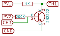
In the following schematic; the collector current can be calculated using known PV1 value and the measured CH1 value as follows;

IC = (PV1 – CH1) / 1000

This is how it is actually implemented in the existing experiments.

If one needs to implement a new experiment of any kind, these are the basics need to know. There can be so many new experiments implemented using these basics. Some of them could be;

  • Effect of Temperature coefficient in Collector current
  • The influence in β factor in Collector current

Resources:

Continue ReadingBasics behind BJT and FET experiments in PSLab

Providing Support for Performing Rectifier Experiments in PSLab Android

PSLab can be used to perform Half and Full Wave Rectifier Experiments. A rectifier is an electrical device that converts alternating current (AC), which periodically reverses direction, to direct current (DC), which flows in only one direction. Half wave rectifiers clip out the negative part of the input waveform. The rectified signal can be further filtered with a capacitor in order to obtain a low ripple DC voltage. Only a diode is needed to clip out the negative part of the input signal. Full wave rectifiers combine the positive halves of 180 degrees out of phase input waveforms such as those output from AC transformers with a center tap. The rectified signal can be further filtered with a capacitor in order to obtain a low ripple DC voltage. Two diodes are used to clip out the negative parts of both inputs and combine them into a single output which is always in the positive region.

In order to support Half Wave Rectifier Experiments in PSLab, we used Oscilloscope Activity. For Half Rectifier Experiment we require to generate a sine wave from W1 channel and read signals from CH1 and CH2.

To implement this we first need to inform the Oscilloscope Activity whether Half Wave Rectifier Experiment needs to be performed or not. For this, we used putExtra and getExtra methods.

  Bundle extras = getIntent().getExtras();
  if ("Half Rectifier".equals(extras.getString("who"))) {
          isHalfWaveRectifierExperiment = true;        
 }

Then we programmatically change the layout. The side panel is made disappear and the graph and lower panel of the Oscilloscope expands horizontally.

if (isHalfWaveRectifierExperiment) {
            linearLayout.setVisibility(View.INVISIBLE);
            RelativeLayout.LayoutParams lineChartParams = (RelativeLayout.LayoutParams) mChartLayout.getLayoutParams();
            lineChartParams.height = height * 5 / 6;
            lineChartParams.width = width;
            RelativeLayout.LayoutParams frameLayoutParams = (RelativeLayout.LayoutParams) frameLayout.getLayoutParams();
            frameLayoutParams.height = height / 6;
            frameLayoutParams.width = width;
        }

The fragment for lower panel is replaced by the fragment designed for Half Wave Rectifier

halfwaveRectifierFragment = new HalfwaveRectifierFragment();
 
if (isHalfWaveRectifierExperiment) {
addFragment(R.id.layout_dock_os2, halfwaveRectifierFragment, "HalfWaveFragment");
 }

We get the following layout, ready to perform halfwave rectifier experiment.

For making the graph functional, capturing signals from CH1 and CH2 is required. For this, we reused CaptureTwo AsyncTask in such a way that it captures signals from CH1 and CH2 channels where CH1 is the input signal and CH2 is the output signal.

if (scienceLab.isConnected() && isHalfWaveRectifierExperiment) {
   captureTask2 = new CaptureTaskTwo();
   captureTask2.execute("CH1");
   synchronized (lock) {
       try {
           lock.wait();
       } catch (InterruptedException e) {
           e.printStackTrace();
       }
   }
}


By following the above steps we reused Oscilloscope Activity to perform Rectifier Experiments.

Resources

Continue ReadingProviding Support for Performing Rectifier Experiments in PSLab Android

Designing A Remote Laboratory With PSLab: execution of function strings

In the previous blog post, we introduced the concept of a ‘remote laboratory’, which would enable users to access the various features of the PSLab via the internet. Many aspects of the project were worked upon, which also involved creation of a web-app using EmberJS that enables users to create accounts , sign in, and prepare Python programs to be sent to the server for execution. A backend APi server based on Python-flask was also developed to handle these tasks, and maintain a postgresql database using sqlalchemy .

The following screencast shows the basic look and feel of the proposed remote lab running in a web browser.

This blog post will deal with implementing a way for the remote user to submit a simple function string, such as get_voltage(‘CH1’), and retrieve the results from the server.

There are three parts to this:
  • Creating a dictionary of the functions available in the sciencelab instance. The user will only be allowed access to these functions remotely, and we may protect some functions as the initialization and destruction routines by blocking them from the remote user
  • Creating an API method to receive a form containing the function string, execute the corresponding function from the dictionary, and reply with JSON data
  • Testing the API using the postman chrome extension
Creating a dictionary of functions :

The function dictionary maps function names against references to the actual functions from an instance of PSL.sciencelab . A simple dictionary containing just the get_voltage function can be generated in the following way:

from PSL import sciencelab
I=sciencelab.connect()
functionList = {'get_voltage':I.get_voltage}

This dictionary is then used with the eval method in order to evaluate a function string:

result = eval('get_voltage('CH1')',functionList)
print (result)
0.0012

A more efficient way to create this list is to use the inspect module, and automatically extract all the available methods into a dictionary

functionList = {}
for a in dir(I):
	attr = getattr(I, a)
	if inspect.ismethod(attr) and a!='__init__':
		functionList[a] = attr

In the above, we have made a dictionary of all the methods except __init__

This approach can also be easily extrapolated to automatically generate a dictionary for inline documentation strings which can then be passed on to the web app.

Creating an API method to execute submitted function strings

We create an API method that accepts a form containing the function string and option that specifies if the returned value is to be formatted as a string or JSON data. A special case arises for numpy arrays which cannot be directly converted to JSON, and the toList function must first be used for them.

@app.route('/evalFunctionString',methods=['POST'])
def evalFunctionString():
    if session.get('user'):
        _stringify=False
        try:
            _user = session.get('user')[1]
            _fn = request.form['function']
            _stringify = request.form.get('stringify',False)
            res = eval(_fn,functionList)
        except Exception as e:
            res = str(e)
        #dump string if requested. Otherwise json array
        if _stringify:
            return json.dumps({'status':True,'result':str(res),'stringified':True})
        else:
            #Try to simply convert the results to json
            try:
                return json.dumps({'status':True,'result':res,'stringified':False})
            # If that didn't work, it's due to the result containing numpy arrays.
            except Exception as e:
                #try to convert the numpy arrays to json using the .toList() function
                try:
                    return json.dumps({'status':True,'result':np.array(res).tolist(),'stringified':False})
                #And if nothing works, return the string
                except Exception as e:
                    print( 'string return',str(e))
                    return json.dumps({'status':True,'result':str(res),'stringified':True})
    else:
        return json.dumps({'status':False,'result':'unauthorized access','message':'Unauthorized access'})
Testing the API using Postman

The postman chrome extension allows users to submit forms to API servers, and view the raw results. It supports various encodings, and is quite handy for testing purposes.Before executing these via the evalFunctionString method, user credentials must first be submitted to the validateLogin method for authentication purposes.

Here are screenshots of the test results from a ‘get_voltage(‘CH1’)’ and ‘capture1(‘CH1’,20,1)’ function executed remotely via postman.


Our next steps will be to implement the dialog box in the frontend that will allow users to quickly type in function strings, and fetch the resultant data

Resources:


Continue ReadingDesigning A Remote Laboratory With PSLab: execution of function strings

Electronics Experiments with PSLab

Numerous college level electronics experiments can be performed using Pocket Science Lab (PSLab). The Android app and the Desktop app have all the essential features needed to perform these experiments and both these apps have quite a large number of experiments built-in. Some of the common experiments involve the use of BJT (Bipolar Junction Transistor), Zener Diode, FET (Field Effect Transistor), Op-Amp ( Operational Amplifier) etc. This blog walks through the details of performing some experiments using the above commonly used elements.  

The materials required for all the experiments are minimal and includes a few things like PSLab hardware device, components like Diodes, Transistors, Op-Amps etc., connecting wires/jumpers and secondary components like resistors, capacitors etc. Most of these elements would be a part of the PSLab Accessory Kit.

It is recommended to read this blog here, go through the resources mentioned at the end and also get acquainted with construction of circuits before advancing with the experiments mentioned in this blog.

Half Wave and Full Wave Rectifiers

The Bipolar Junction Transistor (BJT) can be used as a rectifier. Rectifiers are needed in circuits to obtain a nearly constant and stable output voltage and prevent any ripples in the circuit. The rectifier can be half wave or full wave depending on whether it rectifies one or both cycles of Alternating Voltage.

The circuit for the Half and Full Wave rectifier is given as follows:

  • Construct the above circuits on a breadboard.
  • For the half wave rectifier, connect the terminals of CH1 and GND of PSLab on the input side and the terminals of CH2 and GND on the output side.
  • The terminals of W1 and GND are also connected on the input side and they are used to generate a sine wave.
  • Use the PSLab Desktop App and open the Waveform Generator in Control. Set the wave type of W1 to Sine and set the frequency at 100 Hz and magnitude to 10mV. Then go ahead and open the Oscilloscope.
  • CH1 would display the input waveform and CH2 will display the output waveform and the plots can be observed.
  • The plot obtained will have rectification in only half of the cycle. In order to obtain rectification in the complete cycle, the full wave rectifier is needed.
  • For the full wave rectifier, the procedure is the same but an additional diode is used. Use an additional channel CH3 to plot the extra input.

  • The plot obtained from the above steps would still have ripples and so a capacitor is placed in parallel to cancel this effect.
  • Place a 100uF/330uF capacitor in parallel to the resistor RL and an additional 1 ohm resistor in the circuit.

BJT Inverter

  • Transistor has a lot of functions. The most common of them is its use as an amplifier. However, transistor can be used as a switch in a circuit i.e. as an inverter.
  • The circuit for this experiment is shown below. For this experiment, it is recommended to use an external 5V DC supply like a battery. Connect the transistor and the diode initially and then connect the resistors accordingly. (Connect the terminals of diode and transistor carefully else they will be damaged).
  • When the circuit is constructed completely, connect CH1 to Vi and CH2 to Vo. Vi and Vo are input and outputs respectively and are marked in the figure.
  • The terminals of W1 and GND are also connected on the input side and they are used to generate a sine wave.
  • Use the PSLab Desktop App and open the Waveform Generator in Control. Set the wave type of W1 to Sine and set the frequency at 200 Hz and magnitude to 10mV.
  • Then go ahead and open the Oscilloscope. Use the X-Y mode of the oscilloscope to obtain the plot between Vi and Vo which should look like the graph shown below.

Common Mode Gain and Differential Mode Gain in Op-Amps

Gain of any amplifier can be calculated by calculating the ratio of the output and input voltage. On plotting the graph in X-Y mode, a Vo vs Vi graph is obtained. The slope of that graph gives us the gain at any particular input voltage.

  • For finding the Differential Mode gain of an Op-Amp, construct the circuit as shown below.
  • When the circuit is constructed completely, connect CH1 to Vi and CH2 to Vo. Vi and Vo are input and outputs respectively and are marked in the figure. The terminals of W1 and GND are also connected on the input side and they are used to generate a sine wave.
  • The power supply provided to the Op-Amp are set to + 12V. (If faced with any confusion, please refer to the resources mentioned at the end of the blog to learn more about Op-Amps before proceeding ahead.)
  • Use the PSLab Desktop App and open the Waveform Generator in Control. Set the wave type of W1 to Sine and set the frequency at 1000 Hz and magnitude to 0.5V. Then go ahead and open the Oscilloscope. Use the X-Y mode of the oscilloscope to obtain the plot between Vi and Vo.
  • For finding the Common Mode gain of the Op-Amp, remove the waveform generator input i.e W1 from R3 and attach it to R2. The rest of the steps remain the same.

Schmitt Trigger

In electronics, a Schmitt trigger is a comparator circuit with hysteresis implemented by applying positive feedback to the noninverting input of a comparator or differential amplifier. It is an active circuit which converts an analog input signal to a digital output signal.

  • Construct the circuit as shown below. Although the diagram shows a variable resistor be used, a constant value resistor would also work fine.
  • When the circuit is constructed completely, connect CH1 to Vi and CH2 to Vo. Vi and Vo are input and outputs respectively and are marked in the figure. The terminals of W1 and GND are also connected on the input side and they are used to generate a sine wave.
  • The power supply provided to the Op-Amp are set to + 12V. (If faced with any confusion, please refer to the resources mentioned at the end of the blog to learn more about Op-Amps before proceeding ahead. If done incorrectly, Op-Amps will be damaged)
  • Use the PSLab Desktop App and open the Waveform Generator in Control. Set the wave type of W1 to Sine and set the frequency at 1000 Hz and magnitude to 0.5V. Then go ahead and open the Oscilloscope. Use the X-Y mode of the oscilloscope to obtain the plot between Vi and Vo which should look like the graph shown below.

Resources:

  1. Read more about Half wave and Full wave rectifier and their applications – https://en.wikipedia.org/wiki/Rectifier
  2. Read more about the Bipolar Junction Transistor and its use as a switch – http://www.electronicshub.org/transistor-as-switch/
  3. Understand the common mode and differential mode of Op-Amp – https://www.allaboutcircuits.com/video-lectures/op-amps-common-differential/
  4. Find more about Schmitt Trigger and its uses – https://en.wikipedia.org/wiki/Schmitt_trigger

Continue ReadingElectronics Experiments with PSLab

Designing a Remote Laboratory with PSLab using Python Flask Framework

In the introductory post about remote laboratories, a general set of tools to create a framework and handle its various aspects was also introduced. In this blog post, we will explore the implementation of several aspects of the backend app designed with python-flask, and the frontend based on EmberJS. A clear separation of the frontend and backend facilitates minimal disruption of either sections due to the other.

Implementing API methods in Python-Flask

In the Flask web server, page requests are handled via ‘routes’ , which are essentially URLs linked to a python function. Routes are also capable of handling payloads such as POST data, and various return types are also supported.

We shall use an example to demonstrate how a Sign-Up request sent from the sign-up form in the remote lab frontend for PSLab is handled.

@app.route('/signUp',methods=['POST'])
def signUp():
	"""Sign Up for Virtual Lab

	POST: Submit sign-up parameters. The following must be present:
	 inputName : The name of your account. does not need to be unique
	 inputEmail : e-mail ID used for login . must be unique.
	 inputPassword: password .
	Returns HTTP 404 when data does not exist.
	"""
	# read the posted values from the UI
	_name = request.form['inputName']
	_email = request.form['inputEmail']
	_password = request.form['inputPassword']

	# validate the received values
	if _name and _email and _password:
		_hashed_password = generate_password_hash(_password)
		newUser = User(_email, _name,_hashed_password)
		try:
			db.session.add(newUser)
			db.session.commit()
			return json.dumps({'status':True,'message':'User %s created successfully. e-mail:%s !'%(_name,_email)})
		except Exception as exc:
			reason = str(exc)
			return json.dumps({'status':False,'message':str(reason)})


In this example, the first line indicates that all URL requests made to <domain:port>/signUp will be handled by the function signUp . During development, we host the server on localhost, and use the default PORT number 8000, so sign-up forms must be submitted to 127.0.0.1:8000/signUp .

For deployment on a globally accessible server, a machine with a static IP, and a DNS record must be used. An example for such a deployment would be the heroku subdomain where pslab-remote is automatically deployed ; https://pslab-stage.herokuapp.com/signUp

A closer look at the above example will tell you that POST data can be accessed via the request.form dictionary, and that the sign-up routine requires inputName,inputEmail, and inputPassword. A password hash is generated before writing the parameters to the database.

Testing API methods using the Postman chrome extension

The route described in the above example requires form data to be submitted along with the URL, and we will use a rather handy developer tool called Postman to help us do this. In the frontend apps , AJAX methods are usually employed to do such tasks as well as handle the response from the server.


The above screenshot shows Postman being used to submit form data to /signUp on our API server running at localhost:8000 . The fields inputName, inputDescription, and inputPassword are also posted along with it.

In the bottom section, one can see that the server returned a positive status variable, as well as a descriptive message.

Submitting the sign up form via an Ember controller.
  • Setting up a template
    We first need to set up a template that we shall call sign-up.hbs , and add the following form to it. This form contains the details essential for signing up , and its submit action is linked to an action called `signMeUp` . This action will be defined in the controller which we shall explore shortly

<form class="form-signin" {{action "signMeUp" on="submit"}} >
        <label for="inputName" class="sr-only">Your Name</label>
        {{input value=inputName type="text" name="inputName" id="inputName" class="form-control" placeholder="name" required=true autofocus=true}}
        <label for="inputEmail" class="sr-only">Email address</label>
        {{input value=inputEmail type="email" name="inputEmail" id="inputEmail" class="form-control" placeholder="Email address" required=true autofocus=true}}
        <label for="inputPassword" class="sr-only">Password</label>
        {{input value=inputPassword type="password" name="inputPassword" id="inputPassword" class="form-control" placeholder="Password" required=true autofocus=true}}
         
        <button class="btn btn-lg btn-primary btn-block" type="submit">Sign Up</button>
</form>


  • Defining the controller
    The controller contains the actions and variables that the template links to. In this case, we require an action called signMeUp. The success, failure, and error handlers are hidden for clarity.

import Ember from 'ember';
export default Ember.Controller.extend({
  actions:{
    signMeUp() {
        var request = Ember.$.post("/signUp",
 this.getProperties("inputName","inputEmail","inputPassword"),this,'json');
        request.then(this.success.bind(this), this.failure.bind(this),
this.error.bind(this));
    },
  },
});

The signMeUp action submits the contents of the form to the signUp route on the API server, and the results are handled by functions called success, failure, or error depending on the type of response from the backend server.

Resources:


Continue ReadingDesigning a Remote Laboratory with PSLab using Python Flask Framework

Calibrating the PSLab’s Analog Features for Maximum Accuracy

The hardware design of the PSLab aims to achieve the maximum possible performance from a very conservative bill of materials. There are several analog components such as Op-amps, voltage dividers, and level-shifters involved in input signal processing that have inherent offsets and slopes that must be corrected in order get the best results. Similarly, some analog output signals from the PSLab are also modified by buffers, amplifiers, and level shifting circuits.

One way to improve the initial accuracy is to choose high performance analog components that are factory calibrated , and do not require any additional correction to achieve error margins that are less than the least count of the PSLab’s measurement capabilities. However, such components such as laser trimmed resistor pairs, and low-offset Op-Amps are quite expensive, and we must instead use software based correction methods to achieve similar performance from affordable parts.

Identifying a suitable calibrator for analog signals

In order to calibrate a device, we must first own a similar device whose measurements we can trust, and which has a finer resolution that the PSLab itself. Calibration is a one-time task that will quantify and store the gain and offset errors, and these errors are not expected to behave very differently unless a significant change in temperature, or mechanical stress is experienced.

Such a device may be as expensive as 24-bit, research-grade multimeters which generally cost upwards of $500 , or can be inexpensive analog to digital convertors that might require some expertise to extract data from them, but can still be used for calibration.

Fortunately, we have been able to identify a cheaply available device that puts the calibration process within the reach and capabilities of the end user. The ADS1115 16-bit ADC is a 4-channel, 0-3.3V ADC that can be interfaced via I2C. Typical initial accuracy of the internal voltage reference 0.01% and data rates higher than 500SPS are possible. It is cost effective, and is available in convenient module formats that can be directly plugged into the PSLab itself. It can be purchased through various vendors ( A , B , C )

Therefore, it appears to be most suited to calibrate individual PSLab devices.

Basic requirements for the calibration process

The process to calibrate the analog inputs and outputs involves looping them externally , and monitoring the actual values via the external calibrator.

We’re killing two birds with one stone by calibrating inputs and outputs in tandem, and it makes for a faster calibration process. The complete calibration process for  Digital to Analog converter outputs has enough complexity to warrant a separate blog post.

Let’s take an example; PV1 ( an analog output that can be set between -5V and +5V) can be connected to CH1 (An analog input which can read voltage values between -16 and +16 Volts) with a small segment of wire, and various voltage values can be set on PV1, and read back by CH1 . At the same time, the external calibration utility will also monitor this voltage, and store the error in PV1 (Set Voltage – Actual Voltage) as well as the error in CH1 ( Read Voltage – Actual Voltage ) .

In a similar manner , PV2 can be connected to CH2, and the second channel of the ADS1115 calibrator can be used to monitor the real value, and so on .

Deviations of various analog input channels and their different voltage ranges from the actual values. As is evident from the graph, errors can be as much as 40mV in a full scale range of +/-16,000mV . But since these errors are quite repeatable, we can apply a calibration polynomial to correct these.


Integral Non-linearity of the ADC

In addition to the overall slope and offset, you have probably observed in the previous image, a sawtooth pattern with an amplitude as small as the least count of the analog inputs superimposed on them. This error arises from the integral non-linearity (INL) of the analog to digital convertor of the PIC, and affects all analog inputs uniformly. While in principle we can ignore this for all practical purposes, in order to further improve the analog accuracy, we can also store this INL error of the ADC, and apply this correction to any channel after its slope and offset has been corrected.

The overall slope and offset are caused by the analog references and components, and can be corrected with a simple 3-degree polynomial. However, the sawtooth pattern is characteristics of the INL, and must be stored in a correction array with 4096 elements ( Each element represents the error of the corresponding ADC code of the 12-bit ADC )
The yellow trace represents the error in readings from the ADC after applying polynomial and table based correction. There appears to be a small offset that can be attributed to a change in ambient temperature , but can be neglected as it is in the order of 100uV


The following utilities and code are necessary for this process
  • An I2C communication library for ADS1115 must be present in order to acquire data from it via the PSLab
  • The library should be able to handle the following tasks
    • read single ended , and differential voltage values from any of the channels
    • Enable selection of voltage range and voltage reference
  • A graphical interface with the following features and algorithms will be required:
    • Vary the output voltages from PV1,2,3 in small, definite intervals
    • Store the errors in the analog outputs and inputs as a function of the actual voltage
    • Generate Cubic interpolation functions for each input and output channel
    • The Programmable Current Source can be calibrated using a measured Load resistor, and calibrated analog channel. Its interpolation function must also be stored.
    • Write all calibration constants into flash memory after assigning a timestamp
    • Store raw calibration data in a client-side folder
Testing of the analog inputs after applying calibration polynomials. It can be observed that the accuracy has been brought within a +/-5mV range for the wide input channels. For CH3, a +/-1mV accuracy is achieved.
Resources

Continue ReadingCalibrating the PSLab’s Analog Features for Maximum Accuracy

Implementing Experiment Functionality in PSLab Android

Using the PSLab Hardware Device, users can perform experiments in various domains like Electronics, Electrical, Physics, School Level experiments, etc. These experiments can be performed using functionalities exposed by hardware device like Programmable Voltage Sources, Programmable Current Source, etc. In this post we will try implementing the functionality to perform an experiment using the PSLab Hardware Device and the PSLab Android App.

Let us take the Ohm’s law experiment as an example and see how it’s implement using the  PSLab Android App.

Ohm’s law states that the current through a conductor between two points is directly proportional to the voltage across the two points, effectively using a constant of proportionality called Resistance (R) where,

R = V / I

Schematic

Layout to perform Ohm’s law experiment

The Ohm’s law experiment requires a variable current, so a seekbar is provided to change the current coming from PCS channel, values of which are continuously reflected in the TextView next to it.

Implementation

The Read button has a listener attached to it. Once it is clicked, the currentValue is updated with the value parsed from the seekbar progress and the selectedChannel variable is assigned from the spinner. These variables are used by the background thread to change the current supplied by current source (PCS pin) of the device and to read the updated voltage from the selected channel of the device.

btnReadVoltage.setOnClickListener(new View.OnClickListener() {
   @Override
   public void onClick(View v) {
       selectedChannel = channelSelectSpinner.getSelectedItem().toString();
       currentValue = Double.parseDouble(tvCurrentValue.getText().toString());
       if (scienceLab.isConnected()) {
           CalcDataPoint calcDataPoint = new CalcDataPoint();
           calcDataPoint.execute();
       } else {
           Toast.makeText(getContext(), "Device not connected", Toast.LENGTH_SHORT).show();
       }
   }
});

CalcDataPoint is an AsyncTask which does all the underlying work like setting the current at the PCS channel, reading the voltage from the CH1 channel and triggering the update of the data points on the graph.

private class CalcDataPoint extends AsyncTask<Void, Void, Void> {

   @Override
   protected Void doInBackground(Void... params) {
       scienceLab.setPCS((float) currentValue);
       switch (selectedChannel) {
           case "CH1":
               voltageValue = scienceLab.getVoltage("CH1", 5);
               break;
           case "CH2":
               voltageValue = scienceLab.getVoltage("CH2", 5);
               break;
           case "CH3":
               voltageValue = scienceLab.getVoltage("CH3", 5);
               break;
           default:
               voltageValue = scienceLab.getVoltage("CH1", 5);
       }
       x.add((float) currentValue);
       y.add((float) voltageValue);
       return null;
   }

   @Override
   protected void onPostExecute(Void aVoid) {
       super.onPostExecute(aVoid);
       updateGraph();
   }
}

updateGraph() method is used to update the graph on UI thread. It creates a new dataset from the points which were added by the background thread and refreshes the graph with it using the invalidate() method.

private void updateGraph() {
   tvVoltageValue.setText(df.format(voltageValue));
   List<ILineDataSet> dataSets = new ArrayList<>();
   List<Entry> temp = new ArrayList<>();
   for (int i = 0; i < x.size(); i++) {
       temp.add(new Entry(x.get(i), y.get(i)));
   }
   LineDataSet dataSet = new LineDataSet(temp, "I-V Characteristic");
   dataSet.setColor(Color.RED);
   dataSet.setDrawValues(false);
   dataSets.add(dataSet);
   outputChart.setData(new LineData(dataSets));
   outputChart.invalidate();
}

Roadmap

We are planning to add an option to support multiple trials of the same experiment and save each trails for further reference. App flow to perform experiment is based on Science Journal app by Google.

Resources

  • Article on Ohm’s law and Power on electronics-tutorial
  • To know more about Voltage, Current, Resistance and Ohm’s law, head on to detailed tutorial on sparkfun
  • Implementation of perform experiment functionality in PSLab Desktop App

Continue ReadingImplementing Experiment Functionality in PSLab Android

Performing the Experiments Using the PSLab Android App

General laboratory experiments can be performed using core functionalities offered by the PSLab hardware device like Programmable Voltage Sources, Programmable Current Source, Analog to Digital Converter, Frequency Counter, Function Generators, etc. In this post we will  have a brief look on a general laboratory experiment and how we can perform it using the  PSLab Android App and the PSLab hardware device.

We are going to take Zener I-V Characteristics Curve experiment as an example to understand how we can perform a general experiment using the PSLab device. First, we will  look at the general laboratory experiment and it’s format. Then we will see how that experiment can be performed using the PSLab Android App and the PSLab Hardware Device.

Experiment Format of General Experiment in Laboratory

AIM: In this experiment, our aim is to observe the relation between the voltage and the corresponding current that was generated. We will then plot it to get the dependence.

Apparatus:

  • A Zener Diode
  • A DC Voltage Supplier
  • Bread Board
  • 100 ohm resistor
  • 2 multimeter for measuring current and voltages
  • Connecting wires

Theory: A Zener Diode is constructed for operation in the reverse breakdown region.The relation between I-V is almost linear in this case, Vz = Vz0 + Iz * Rz , where Rz is the dynamic resistance of the zener at the operating point and Vz0 is the voltage at which the straight-line approximation of the I-V characteristic intersects the horizontal axis. After reaching a certain voltage, called the breakdown voltage, the current increases drastically even for a small change in voltage. However, there is no appreciable change in voltage accompanying this current change. So, when we plot the graph, we get a curve which is very near to the x-axis and nearly parallel to it until a particular potential value, called the Zener potential, is reached. After the Zener potential Vz value, there will be a sudden change and the graph becomes exponential.

Source: learning about electronics

Procedure: Construct the circuit as shown in figure below

Now, start increasing the voltage until a reading in the multimeter for current can be obtained. Note that reading. Now, start increasing the input voltage and take the corresponding current readings. Using the set of readings observed,  construct a V vs I graph. This graph gives us the I-V characteristics. The slope of the curve at any point gives the dynamic resistance at that voltage.

Result: The Characteristic curve has been verified after plotting V-I data points on the graph.

Experiment format in PSLab Android App

We have a ViewPager that renders two fragments:

  1. Experiment Doc– It consists of information like the Aim of experiment, Schematic, Output screenshot that we will get after the experiment has been performed.
  2. Experiment Setup– It consists of the setup to configure the PSLab device. This fragment is analogous to the experiment apparatus of the laboratory.  

Below is a gif showing the experiment doc of the Zener I-V experiment which is to be performed using the PSLab device. It consists of a schematic and a screenshot of the output that we get after performing the experiment.

Source: PSLab Android

Make the circuit connections on a breadboard as shown in the schematic. After the circuit is complete we need to configure experiment.

Source: PSLab Android

To configure the experiment, we give the initial voltage, the final voltage and the step size. After clicking on START EXPERIMENT, the voltage is varied on the PV1 channel from the initial voltage to final voltage by increasing the voltage in step size. At each variation of voltage, the current is calculated by dividing the voltage difference between resistor by its resistance value i.e

I = ( VPV1 - VCH1 ) / R

As soon as the initial voltage reaches the final voltage, the experiment stops and data points are plotted on the graph. From the graph we can see the change in the current through a zener diode when the voltage varies across it’s terminals.

The output that was obtained after the experiment is I-V characteristic curve for Zener Diode as shown in the image below.

It can be clearly seen that after the breakdown voltage (~0.7V) the  current increases drastically with respect to the  increase in the voltage. After this point, the voltage can be considered  nearly constant unlike the current which varies exponentially.

In the PSLab Android App, there are read-back errors while reading bytes serially from the PSLab Hardware Device. As a result, the data points are not read accurately and an inaccurate plot is generated on the graph as shown in the image below.

Source: PSLab Android

Resources

Continue ReadingPerforming the Experiments Using the PSLab Android App

SPI Communication in PSLab

PSLab supports communication using the Serial Peripheral Interface (SPI) protocol. The Desktop App as well as the Android App have the framework set-up to use this feature. SPI protocol is mainly used by a few sensors which can be connected to PSLab. For supporting SPI communication, the PSLab Communication library has a dedicated class defined for SPI. A brief overview of how SPI communication works and its advantages & limitations can be found here.

The class dedicated for SPI communication with numerous methods defined in them. The methods required for a particular SPI sensor may differ slightly, however, in general most sensors utilise a certain common set of methods. The set of methods that are commonly used are listed below with their functions.

In the setParameters method, the SPI parameters like Clock Polarity (CKP/CPOL), Clock Edge (CKE/CPHA), SPI modes (SMP) and other parameters like primary and secondary prescalar which are specific to the device used.

Primary Prescaler (0,1,2,3) for 64MHz clock->(64:1,16:1,4:1,1:1)

Secondary prescaler (0,1,..7)->(8:1,7:1,..1:1)

The values of CKP/CPOL and CKE/CPHA needs to set using the following convention and according to our requirements.

  • At CPOL=0 the base value of the clock is zero, i.e. the idle state is 0 and active state is 1.
    • For CPHA=0, data is captured on the clock’s rising edge (low→high transition) and data is changed at the falling edge (high→low transition).
    • For CPHA=1, data is captured on the clock’s falling edge (high→low transition) and data is changed at the rising edge (low→high transition).
  • At CPOL=1 the base value of the clock is one (inversion of CPOL=0), i.e. the idle state is 1 and active state is 0.
    • For CPHA=0, data is captured on the clock’s falling edge (high→low transition) and data is changed at the rising edge (low→high transition).
    • For CPHA=1, data is captured on the clock’s rising edge (low→high transition) and data is changed at the falling edge (high→low transition).

public void setParameters(int primaryPreScalar, int secondaryPreScalar, Integer CKE, Integer CKP, Integer SMP) throws IOException {
        if (CKE != null) this.CKE = CKE;
        if (CKP != null) this.CKP = CKP;
        if (SMP != null) this.SMP = SMP;

        packetHandler.sendByte(commandsProto.SPI_HEADER);
        packetHandler.sendByte(commandsProto.SET_SPI_PARAMETERS);
        packetHandler.sendByte(secondaryPreScalar | (primaryPreScalar << 3) | (this.CKE << 5) | (this.CKP << 6) | (this.SMP << 7));
        packetHandler.getAcknowledgement();
    }


The start method is responsible for sending the instruction to initiate the SPI communication and it takes the channel which will be used for communication as input.

public void start(int channel) throws IOException {
        packetHandler.sendByte(commandsProto.SPI_HEADER);
        packetHandler.sendByte(commandsProto.START_SPI);
        packetHandler.sendByte(channel);
    }


The setCS method is responsible for selecting the slave with which the SPI communication has to be done. This feature of SPI communication is known as Chip Select (CS) or Slave Select (SS). A master can use multiple Chip/Slave Select pins for communication whereas a slave utilises just one pin as SPI is based on single master multiple slaves principle. The capacity of PSLab is limited to two slave devices at a time.

public void setCS(String channel, int state) throws IOException {
        String[] chipSelect = new String[]{"CS1", "CS2"};
        channel = channel.toUpperCase();
        if (Arrays.asList(chipSelect).contains(channel)) {
            int csNum = Arrays.asList(chipSelect).indexOf(channel) + 9;
            packetHandler.sendByte(commandsProto.SPI_HEADER);
            if (state == 1)
                packetHandler.sendByte(commandsProto.STOP_SPI);
            else
                packetHandler.sendByte(commandsProto.START_SPI);
            packetHandler.sendByte(csNum);
        } else {
            Log.d(TAG, "Channel does not exist");
        }
    }


The stop method is responsible for sending the instruction to the stop the communication with the slave.

public void stop(int channel) throws IOException {
        packetHandler.sendByte(commandsProto.SPI_HEADER);
        packetHandler.sendByte(commandsProto.STOP_SPI);
        packetHandler.sendByte(channel);
    }


PSLab SPI class has methods defined for sending either 8-bit or 16-bit data over SPI which are further classified on whether they request the acknowledgement byte (it helps to know whether the communication was successful or unsuccessful) or not.

The methods are so named send8, send16, send8_burst and send16_burst . The burst methods do not request any acknowledgement value and as a result work faster than the normal methods.

public int send16(int value) throws IOException {
        packetHandler.sendByte(commandsProto.SPI_HEADER);
        packetHandler.sendByte(commandsProto.SEND_SPI16);
        packetHandler.sendInt(value);
        int retValue = packetHandler.getInt();
        packetHandler.getAcknowledgement();
        return retValue;
    }


Resources:

Continue ReadingSPI Communication in PSLab